What's new

1968 Ford F-250 Prerunner Build

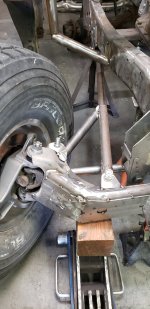
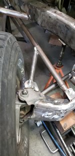
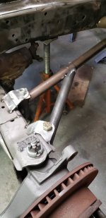
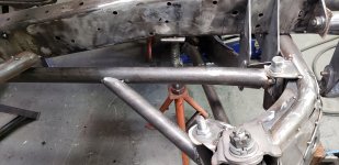
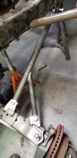
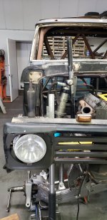
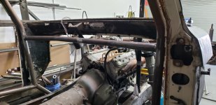
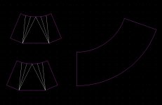
Took the lower/upper link mounts off the frame and got those all welded up and trimmed to fit. Welded transmission crossmember mount up on frame since edge of link mount hits that and hides the joint to weld. Also got the lower backhalf tube in since I removed it for new link mounts and longer lower links/cutting the frame off more.

IMG_20210319_153256_394.jpg


IMG_20210319_153256_404.jpg


IMG_20210319_153256_368.jpg


20210319_141905.jpg
 
How long are the RA going to be? Looks like mounts are front output of TC, so 48"-ish?
Any magic ratio of RA length to the transverse TTB beam length?
 
From my experience the longer and flatter the arm at ride height the better. The radius arm controls caster to if it's short the caster curve will be bad. Doing center mounted radius arms is best to limit caster change but that's no doable really with driveshaft and such. The arms are long around 42" or so from center of beam pivot to radius arm pivot which allows the driveline to cycle fully and not plunge that much.
 
Well no photos again today but I did get the beams and caster positioned with wheels in middle of wheelbase like i want and I tacked a radius arm tube onto that to allow me to cycle them. The passenger beam very slightly contacts the drivers diff beam when is it dropped and driver beam moves up. So i am going to attempt to reset with a few degrees less caster to hopefully let it clear. If it doesn't clear I will move the passenger beam pivot forward 1/4" on the driver side frame rail to allow it to clear perfectly. Also got the front diff bolted into the beam and that allows me to do some mock up extended stock axles to see if they will allow everything to clear or what needs to happen there to get full travel with functioning 4x4.
 
The Ford purists will be showing up any minute telling you that putting an LS motor in a Ford is the ultimate sin and that you just ruined that truck. :lmao:

Looking good man, can't wait to see the end result. :smokin:
Oh they will come out sooner or later. My buddy is swapping a boosted 2JZ into a 69 F100. It will bring the hate for sure.
 
So no photos again left my SD card in the camera at the shop, Guess that's what happens when it's your dad's birthday and you are needing to get home for b-day dinner. Lol

So today I got the diff installed and had to clearance one bottom web gusset to get the axle to turn fully. Also mocked up the passenger axle and had to adjust the driver beam bracket forward to clear the axle shaft near the nut and have it still clear the passenger beam. To adjust the forward but have the diff beam clear the passenger beam at full droop and bumpoing driver diff beam I had to put a slight kick in the driver diff beam so the diff wouldn't move forward just the pivot. Will get some photos of that tomorrow for you guys. Also the beams at 19" of travel at the frame the axles cycle fully but the passenger axle needs around 6" of slip to work properly and will need the slip not at the u-joint like stock to clear everything at bump and droop with one beam up and the other beam drooped.
 
I have a 67 f100 trail truck. I will be following your build. Seen your youtube. My fab nowhere near your skill, but super interested in the cage work as that is one of the upcoming projects for the f100.

Nice build!
 
I have a 67 f100 trail truck. I will be following your build. Seen your youtube. My fab nowhere near your skill, but super interested in the cage work as that is one of the upcoming projects for the f100.

Nice build!

Thanks, the cab cage is already done but I will do a video showing it and give some tips/pointers that I have used to make the cage nice and tight and show a bend protractor I made to figure out the angles.
 
OK spent yesterday cycling beams to get position for swinger for minimal bumpsteer over 24" of travel. Than last night I decided to shorten the beam pivots so they have less leverage and to shorten the swingers which were 14" long. So i moved the beam pivot up 4" and then cycled 100 times to make beams and axles and stuff clear. Than redid steering swinger position again. Made the swingers and will get them tacked on tomorrow with some Mild Seamed tubing for mock up tie rods so I can get my 4130 machined and know right where to bend it, angles, and lengths.

To figure out the steering location for swinger I tacked some pieces of metal where I thought it would be close and than I changed the height and angle till I found the sweet spot. Copied dimensions over to passenger side and checked and it was all good so from the dimensions I drew up some swingers and made some bushings for them. Started tacking together one swinger but I need more misalignment spacers and some cheap tubing so stopped there and will get that stuff tomorrow.

IMG_4414.JPG


IMG_4416.JPG


IMG_4413.JPG


IMG_4415.JPG
 
OK so redid the swingers and still mocking it up to eliminate bumpsteer. He's the old swingers on the truck. I have since made a single width swinger correct length for both sides since the PS ram and the rod from pitman arm will connect to the center connecting link now as well.

IMG_20210329_133314_298.jpg


IMG_20210329_133314_325.jpg


IMG_20210329_133314_339.jpg
 
OK got some mock up tabs to adjust the height on the swingers AND got the location figured out after cycling it 20 times. Then replaced the slotted tabs with the correct single hole tabs. No bumpsteer over 30" of travel which is more than it will cycle with shocks/axles.

20210402_144733.jpg


20210402_172052.jpg


20210402_172101.jpg


20210402_144738.jpg
 
30" of travel at the WMS I assume?

That's without axle shafts, right?
 
Any concerns about bending tie rods with them being so long and having a decent bend already in them to clear the suspension?


30" of travel with no bump steer is :smokin:!
 
Any concerns about bending tie rods with them being so long and having a decent bend already in them to clear the suspension?


30" of travel with no bump steer is :smokin:!


not worried since I have some very expensive 1.25 x .375 4130 tubing which is very tough and I used thinner dom tubing before with more bend and not much
 
Got the front frame box portion tacked on and steering box mounted in place. Also installed the wheels/tires on the truck and bumped it out and it's forward about 1 1/2" from where i want it to sit in the fiberglass so get to move everything back to fix that before i do the radius arms for good.

20210409_130400.jpg
 
OK so mocked up fender on the tire and found the center of it and I had the front end mocked up 1.5" forward from the tire being center. Got all the mounts repositioned 1.5" back and starting on the radius arms in a few days when some material arrives. I am going to do bolt on radius arms and going to try to tie the coilover mount into it as well since the shocks are really too long for this front end but I don't want to bother selling them and then waiting 6 months to get more brand new ones shorter.
 
OK some reason the website wouldn't load on firefox which I generally use so now I'm on chrome and works fine.

Moved the entire front suspension back 1.5" to return wheels to center of fender and it still clears firewall at bump/turn.

Started on radius arms as well. 2" .250 wall main tube that will be gusseted to the heavy wall 2" x .625 tube that goes vertical that bolts to the beam as well at the outer tube that goes from the inner C to radius arms. WIll have the coilover mount and lots of plating to retain it's strength.
 

Attachments

  • 20210415_153030.jpg
    20210415_153030.jpg
    1.2 MB · Views: 96
  • 20210415_153034.jpg
    20210415_153034.jpg
    1.1 MB · Views: 73
  • 20210415_153041.jpg
    20210415_153041.jpg
    1.1 MB · Views: 67
OK so got the core support mocked back up and coilover mocked up. Cycles more travel than the 4x4 will allow so i'll just strap it to limit down travel and/or have shocks not fully compressed at bump. Also ordered some new parts for this so I can have them for mockup when building engine cage/shock mounts. Moved the dash bar down as well to allow tieing into it from engine cage much easier without an extra bend up on every tube. Got the .250 wall tubes in for the radius arms. Had to do a 5deg bend on the pass side to clear the axle completely at full droop and bump on driver side.
 

Attachments

  • 20210420_140821.jpg
    20210420_140821.jpg
    2.6 MB · Views: 73
  • 20210420_140837.jpg
    20210420_140837.jpg
    1.1 MB · Views: 59
  • 20210420_163230.jpg
    20210420_163230.jpg
    1.2 MB · Views: 91
  • 20210420_163238.jpg
    20210420_163238.jpg
    3.1 MB · Views: 61
Also I drew in computer a T6-3" reducer AND a 5" to 3" exhaust reducer as well i'll make out of Stainless steel in future
 

Attachments

  • Exhaust reducers.jpg
    Exhaust reducers.jpg
    68.5 KB · Views: 53
Top Back Refresh