What's new

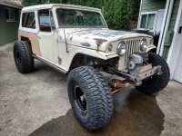
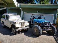
Project Glacier Cold Beer - a '67 Jeepster Commando

Unless you plan to autocross it, the reverse ackermann shouldn't be the end of the world for street driving. Most street driving is in a straight line anyway. Your tire may wear out faster and it might make everyone stare at you when you pull into a parking spot. Like you said, it depends on where you put your priority, street or dirt.

I did what I had to do to get good ackermann on my pile, because I know I'll be driving it on the street more than in the dirt if I'm honest with myself.
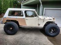
 
Made new steering arms for straight ackerman, have like 37-38* both ways, both sides rub the links at full lock.

20220117_141339.jpg


With the steering figured, the drag link and tie rod are located, time to build the panhard. Made the axle side bracket enough to hold that end, set the axle at ride height, figure out where the frame side goes (ensuring they are parallel), build a bracket.

Frame side -
20220117_141325.jpg


Axle side cluster of linkage...
20220117_170200.jpg


20220117_170151.jpg


More plating to go on the steering arms, and the axle side panhard mount.
Yes, the axle side panhard mount is single shear.
 
Daily driver 1992 Comanche told me it wanted a new water pump. And a serpentine belt.

Also changed the oil (last time was October 2020), and the air filter. It still needs a heater control valve, but napa didn't have one in stock.
20220121_110453.jpg
20220121_110247.jpg
20220121_110241.jpg
 
Decided I needed to start figuring out exhaust. Figured I'd cut the flanges of the factory manifolds and fit and weld them back together at the correct angle to get the pipes around the stuff in the way and inside the frame.

20220121_170337.jpg


20220121_175845.jpg


Drivers side won't work that way. Plan 2 - install a V-band clamp.
V-band is 304, manifold is cast something, Welded up with 309L, worked good, until I went to add a little more in one spot. Barely got the torch going an a big pop, abs a Crack propagated into the manifold.

Hmm. Passenger side readjusting the flange will fit. Got er fit up, and started tacking with 70S-2, and 3rd tack caused the first to Crack clean through. Hmm.

20220122_123314.jpg


People say the NI-99 stuff works for cast things. The internet says preheat, weld, slow cool.

preheat, ya say...

20220122_141822.jpg
 
Didn't even get the passenger side joint complete with NI-99 and preheat before centerline cracking. Welded it out anyway, reflowed the cracks, shoved it into a welding blanket, and tossed the bi-met joint (driver side) on the BBQ after grinding out the cracks.

20220122_143041.jpg
20220122_145708.jpg
20220122_151034.jpg


After a bit, pulled the driver manifold off the spit, and pounded some more 309L in there. Wrapped that with the other in the blanket, then cleaned up a bit, and decided to cut the floor where the rear upper links come through at full compression.

20220122_164904.jpg


20220122_165000.jpg


holes need more work, then cover plates.
 
NI-99 cracked in cooling... centerline.
20220122_165148.jpg


But, 309L bi-met to 304, and repair of previous Crack did not.
20220122_165339.jpg


So, decided to grind out all the NI-99, refit the joint, preheat until glowing red with the acetylene torch, and pounded the passenger header joint with 309L. 2 passes, peened, currently in blanket overnight.


Bolted driver manifold in place, to start working on the next piece.

20220122_210112.jpg


20220122_210120.jpg
 
I have had great luck with 308L. Welding cast is tricky, but once you figure it out not real hard.
 
309L seems to have worked, cooled overnight and No cracks.

On a Facebook group for the LV3 swaps, Bryan McCall posted a link to his '82 yota with this engine that I need to read a bit more.
 
Last edited:
To go with the 1 tool link bolt, you could stick one of these tabs on the backside you can’t put a nut on if you can hold a nut in place. I swear ruffstuff used to make them but I couldn’t find them.
39EAA3CC-57F0-4835-8E65-8D06B89D3605.png
 
Some pics of the passenger manifold, 24 hour VT sat for no cracks. peening marks ruin the as welded surface finish, and look like porosity at first glance...

20220124_184729.jpg
20220124_184743.jpg


With that good enough, played around with the steering column pieces. whoever added power steering to this commando re- usedsome other joints. They are a bit bigger that modern aftermarket stuff. Bought some Amazon parts and a different u joint to get more clearance.

20220124_184931.jpg


20220124_185250.jpg


20220124_190949.jpg

Made A little more room

20220124_190956.jpg
 
Pulled the body after adding a down pipe on the drivers side that clears the steering. Started adding pipe on the passenger. Using a mix of 304 and 409 pipes, because they are already here, and the factory manifolds adapter is 409, so short of adding a v-band on that side, that's what I got.
20220124_211143.jpg


20220124_211156.jpg


Down pipe on drivers side left long intentionally,
20220124_211230.jpg
 
20220129_144439.jpg


20220130_140219.jpg


20220130_140238.jpg


More exhaust work. Will plug the notch with some other tube, as long as when I get the body back on it clears. Will shorten the set screws too.

Got the exhaust up to the flex joint, the flex joint I bought looked way too... China, so I bought another more expensive one. Paused on exhaust for now.
 
But since the body was off, decided to get the rear air bump mounts in. Existing axle pads lined up right behind the body mount, and because the overall length of the air bump body is what it is, that means the top of the bump will barely stick into the tub.

20220130_120734.jpg


20220130_124018.jpg


Mig welded the inside of the bracket, will TIG the outside and the rest of the bump can to the mount once I get the rest of the rear suspension done and can evaluate final full compression with tire to fender clearance at articulation.

20220130_132602.jpg


20220130_132605.jpg


And punched some 3" holes in the tub.

20220130_132622.jpg
 
Do you have a side profile of your front driveline? I've been going back and forth on whether to run a two piece front or not on mine. Picked up a '68 stocker back July and slowly building it into a light wheeler for the old man.
 

Attachments

  • 241891872_4403760226385391_2922607757190211335_n.jpg
    241891872_4403760226385391_2922607757190211335_n.jpg
    107 KB · Views: 19
  • 241947618_4403759539718793_1746419110614413389_n.jpg
    241947618_4403759539718793_1746419110614413389_n.jpg
    122.5 KB · Views: 22
  • 206039699_4169525673142182_1581499742688143351_n.jpg
    206039699_4169525673142182_1581499742688143351_n.jpg
    262 KB · Views: 20
Do you have a side profile of your front driveline? I've been going back and forth on whether to run a two piece front or not on mine. Picked up a '68 stocker back July and slowly building it into a light wheeler for the old man.
I’ll try and get one tonight, but unless you chop out the firewall and move the engine way back or have a super long transmission and / or a doubler, I think a one piece would work. I posted this photo before -
E3A6C4EF-0B37-4EE7-B13E-6E2DE41BAC9F.jpeg


But you can see the front tube of the belly cradle in relation to the CV joint. There is like 3” below the CV joint, and the shaft won’t be able to hit it.

I run a 2 piece on my buggy, but that’s because the front output of the T-case is under the drivers seat, so to have a strong enough belly to have front lower link mounts, I needed to mount a bearing on that same tube. In that car the harmonic balancer is ~9” behind the back of the front axle. With the engine placement on this car being so far forward, harmonic balancer in front of the front axle, the t-case front output is far enough forward to not need a 2 piece.

Or, keeping it on leaf springs also solves a lot of these ‘problems’.
 
That would be awesome. My front axle sits a decent amount in front of the engine and the the t-case isn't quite as compact as your setup (np241). The front looks like it would be doable in my case, but would just seem long and susceptible to getting hit. I may just need to mock it up and see what it really looks like. Thanks for the input!
 
That would be awesome. My front axle sits a decent amount in front of the engine and the the t-case isn't quite as compact as your setup (np241). The front looks like it would be doable in my case, but would just seem long and susceptible to getting hit. I may just need to mock it up and see what it really looks like. Thanks for the input!
Still just mocked up, and at full compression, but with the CV, no way it gets to that lower chassis bar.
20220202_202632.jpg
20220202_202645.jpg
 
Still plugging away...

Body back on, looks like I measured right for the bump cans.
20220131_193733.jpg


So, rear shock time.

20220130_184935.jpg


Went back and forth a lot, thinking on if this plan was even going to work. Measured stuff, stared at it, drank beer, procrastinated by cleaning the shop... Bolted a tire on, flexed the other side way down, and there isn't enough room between the wheel well and the tire for the shock to not hit one of those at full flex.

20220130_180748.jpg


Ordered some wheel spacers from Spidertrax to match the blue of the other parts. Then determined the caliper mounting location wasn't gong to work, so re-mounted 90* forward using one existing mount on the bearing cup. Will have to fab another mount for the caliper bracket later.

Tacked some super high end mockup lower mounts on there and tossed the shocks on.
20220202_205920.jpg
 
Last edited:
Cycled it some -

20220202_201240.jpg


See change in caliper location

20220202_205621.jpg


20220202_210003.jpg


Looks like there is a chance of keeping the inner wheel well.

Next step is to cut some holes for the shocks to stick into the cab...

20220202_211055.jpg


For some reason, I'm chicken, and hesitant to cut these, knowing it's kinda a one way trip, so that's where I stopped for the night.

Maybe butcher the rust free 55 year old sheet metal on a hope that is the right spot tomorrow.
 
Last edited:
Still just mocked up, and at full compression, but with the CV, no way it gets to that lower chassis bar.
20220202_202632.jpg
20220202_202645.jpg

Awesome, thanks for the pics. After looking at my setup again and comparing it to yours I think I'm sorta stuck with doing a 2 piece unfortunately. Your front output is slightly lower than mine being you have the subframe and your transfer case definitely is shorter than mine (I'm running a np241 that's clocked flat). Also, the 700r4 I'm using makes the situation even worse when you look at the pan size in comparison to your setup lol
 
I'll add coilover rebuild with new shock shafts to the list - the bumpers held salt water on them i guess. Sanded it off to not chinger the seal housing while mocking up.
20220205_123821.jpg


Tack welded some mounts on, 14's travel a lot. Need to cut out the inner wheel well gain just a little more clearance and then rotate the upper mounts in a little more to make room for the tire to not hit the bypass.

Unfortunately, I didn't cut enough in the fenders... have to solve that too.

20220206_162400.jpg
20220206_162411.jpg
 
Well, the rear suspension is pretty well dialed. Unfortunately, with the swing of the axle side to side, I wasn't able to keep the rear inner fenderwell, and the tire will also just kiss one of the bypass tubes at full articulation.

20220221_110444.jpg


Made some lower bypass mounts that pickup the truss on the rear axle, but mount the bolt perpendicular to the axle shafts. .188 with .125 teardrop overlays for the bolts. Big hole in the bottom can fit a 3/4 box end through incase that works better than the top. Half circle cut out where it welds to the axle tube to allow water to drain - same with little hole under the shock.

20220223_143528.jpg

20220223_143554.jpg


Mockup upper mounts to determine location on flex and stuff, became nicer mockup mounts.

20220222_093531.jpg


20220224_123111.jpg
 
Upper rear shock mounts - the 2.5 bypass is 1.5" mounting width, and the 2.0 coilover is 1.25" mounting width. I could have found or machined some other shock spacers, but decided to just add a .125 teardrop overlay on the inside of the coilover to make up the 1/4" overall difference - then I can use the existing shock spacers.

The outside got another .125 thick overlay picking up both holes. Capped the ends, and tacked them on with the right rotation to keep the upper eye closer to neutral, but also have them rotated in enough to barely kiss the tire.

20220224_123021.jpg
20220224_143646.jpg
20220224_145356.jpg
20220224_182318.jpg
20220224_204721.jpg
 
Also had to notch the fender for tire clearance at articulation. Moved the axle around with the lower links to get it centered at full compression driver, full droop passenger.
20220222_093546.jpg
20220222_100729.jpg
 
Should still have room for the small back seat, will have to make some tin later to close those back in to keep water out of the cab.

20220224_220213.jpg
20220224_220227.jpg


Tossed some 1.5x.120, notched into the node to support the shock mounts.

20220225_121719.jpg
20220225_121709.jpg
20220225_121730.jpg


The lower end lands centered between the bypass and coilovers mount. Debating running a tube connecting the bottom of the shock mount tube to lower on the b pillar as well.
 
Top Back Refresh