What's new

Project Glacier Cold Beer - a '67 Jeepster Commando

Sub frame coming along. Ordered 3' of 1"x.188" 4130 tube to make sleeves for the link mounts, which will go through the 1.75 tube. Mocked the sub frame under the rig with ratchet straps to figure on things for a beer or 3.

Some chance that a one piece front driveshaft will work. Going to be a pain to pull the transmission if the engine is staying in, but trying to make sure that can happen out the bottom, but also run a full skid...
 

Attachments

  • 20210919_081730.jpg
    20210919_081730.jpg
    3.9 MB · Views: 63
  • 20210919_090300.jpg
    20210919_090300.jpg
    1.4 MB · Views: 62
  • 20210919_090307.jpg
    20210919_090307.jpg
    7.5 MB · Views: 61
4130 1"x.188 showed up. Parted off some 2.25" (ish) lengths in the lathe and Emory cloth polished the mill scale away.

Marked some spots, ran every 18v battery in the shop outta juice, but hogged out the 1" hole and got some more round section GTAW practice installing the sleeves.

Cut some tabs for the other side. I've been very happy with the ruffstuff fix-it weld washers. They add thickness around the hole, but also make the home fabrication faster - I oversize the hole on the plasma table slightly, run the die grinder a quick buzz, then weld em on. I don't have much luck drilling large holes in plate, and opening up plasma cut holes burns through drill bits like they are going out of style, so... these seem to fit the bill for me.

All of this to avoid having 2 tabs and spacing to allow for a nut inside the frame - basically to have the lower links as far outboard, while still being inside the cradle.

"One piece at a time..."

Also, went to the Sunrise side of Mt. Rainier National Park yesterday. Never been there before. It was worth the drive. Go if you haven't been.
 

Attachments

  • 20210924_211644.jpg
    20210924_211644.jpg
    6.4 MB · Views: 74
  • 20210924_212139.jpg
    20210924_212139.jpg
    1.6 MB · Views: 72
  • 20210924_200759.jpg
    20210924_200759.jpg
    6.9 MB · Views: 71
  • 20210924_212045.jpg
    20210924_212045.jpg
    6.4 MB · Views: 71
  • 20210923_133824.jpg
    20210923_133824.jpg
    2.4 MB · Views: 70
  • 20210923_114036.jpg
    20210923_114036.jpg
    6.3 MB · Views: 73
Rallied the 2020 WK2 around Naches for a last minute camping trip with some dirt roads. No progress this weekend, so here is another photo of Rainier from a different angle.
 

Attachments

  • 20211002_183947.jpg
    20211002_183947.jpg
    3.1 MB · Views: 48
For some reason was inspired to progress sheet metal work on the passenger cab floor. Made room for the d300 to clear the floor too.

Have to fill hole in the tunnel where the prior owner mounted a transmission shifter, and cut a patch on the drivers side to fix rust around the inboard driver seat bolts...

I expect to put a textured body / bedliner on the interior, so not working to hard on appearance of these finished welds.
 

Attachments

  • 20211009_144015.jpg
    20211009_144015.jpg
    8.4 MB · Views: 70
  • 20211009_145508.jpg
    20211009_145508.jpg
    3.6 MB · Views: 63
  • 20211009_145531.jpg
    20211009_145531.jpg
    7.6 MB · Views: 63
  • 20211009_155304.jpg
    20211009_155304.jpg
    3.7 MB · Views: 63
Last edited:
Tossed the front axle on the table (I love my shop crane) - the tabs for the lower link mounts are 2" mounting width, with a 5/8 bore. I bought heims to fit that, but later bought Summit Machine joints for the lowers, which are 2-5/8" mounting width with a 5/8 bore.

Chop one tab off.

Also increased the weld size on the single upper link mout, to incorporate the doubler plate - took a before picture, but not an after tonight. Maybe tomorrow.
 

Attachments

  • 20211009_180522.jpg
    20211009_180522.jpg
    4 MB · Views: 93
  • 20211009_180514.jpg
    20211009_180514.jpg
    7.5 MB · Views: 82
  • 20211009_173725.jpg
    20211009_173725.jpg
    7.4 MB · Views: 86
  • 20211009_173721.jpg
    20211009_173721.jpg
    3.6 MB · Views: 82
Last edited:
Kept the theme of the front axle lower control arm mounts with the 5/8" thick 1.75x.120 rings around the bolts TIG welded on. Made new tabs for the outboard side of the mounts.

On the passenger side, the summit machine joint body wanted to hit the axle housing, so back to the lathe to machine a spacer. I added a 1/4" thick spacer to move the joint out away from the housing. Have to do them both sides of course.
 

Attachments

  • 20211010_164436.jpg
    20211010_164436.jpg
    4 MB · Views: 76
  • 20211010_164445.jpg
    20211010_164445.jpg
    3.5 MB · Views: 78
  • 20211010_173533.jpg
    20211010_173533.jpg
    1.9 MB · Views: 77
A few more hours on this, rear axle gets the same treatment. Finished out the detail support plates to match the style Pat had started on this rear axle.

Next step is to build frame side upper link mounts, then I can start cutting up the $17/foot 2"x.250 wall and hope my measurements are right!
 

Attachments

  • 20211019_202835.jpg
    20211019_202835.jpg
    6.4 MB · Views: 64
  • 20211017_161947.jpg
    20211017_161947.jpg
    6.8 MB · Views: 64
  • 20211017_161937.jpg
    20211017_161937.jpg
    1.6 MB · Views: 66
  • 20211017_101122.jpg
    20211017_101122.jpg
    6.7 MB · Views: 62
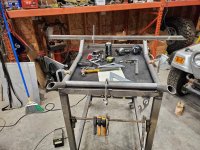
Few hours in this weekend.

When I originally planned this build I was perhaps a bit overzealous, and had figured trailing arms into the rear. Getting further along in it, looking at real estate in the rear wheel tubs and tire clearance with my fairly narrow axles, it's looking like axle mounted shocks is the plan now.

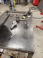
Anyhow, originally planned on heims every where, but switched to summit machine joints for the lowers hoping I don't have to service them as often as inexpensive heims.
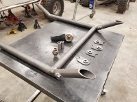
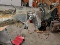
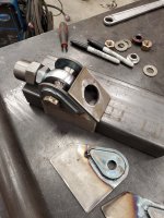
So I bought 6 thread in large summit joints for 5/8 bolts and 2 weld in large summit joints, with the plan that rear frame side mounts would be welded to the link and have some poly bushings on the side of the welded in joint to keep the link from twisting.
No more need for that, but it's what I've got, so, front links will have the threaded joints on both ends, and the rear will have one welded and one threaded for fine adjustment.

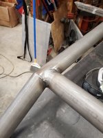
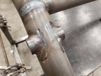
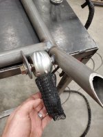
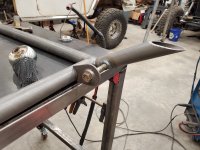
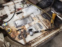
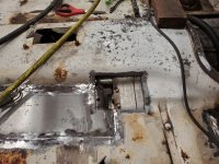
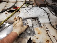
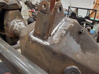
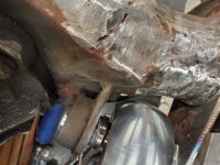
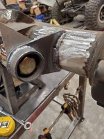
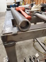
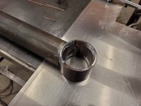
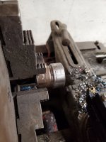
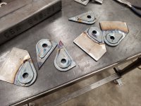
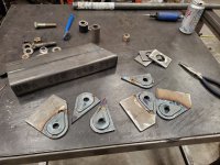
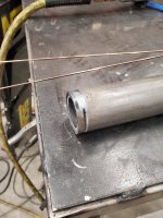
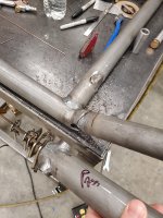
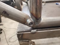
Was one threaded insert short, so found one in an old link, cut it out, smoothed it out in the lathe. TIG on the weld in joints to control heat in the threads and no spatter. TIG on the weld in bungs because the other end is TIG welded. Welded in joint was rooted in this photo, but I didn't get a photo of one fully welded out- but it got 3 passes with 1/16" ER-70s-6

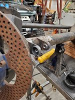
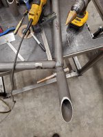
Stuffed some 1.5" 6061-T651 round bar at $8/foot inside the 2"x.250 DOM at $16/foot and weld the bugs in. ID of the tube was closer to 1.490", so some time in the lathe and a nice hammer fit to keep them from rattling until the first rock smash keeps the aluminum from rattling forever.

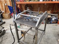
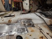
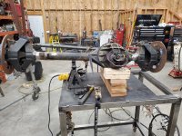
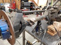
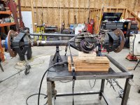
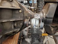
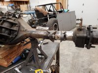
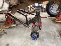
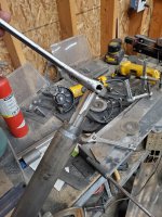
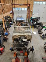
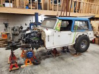
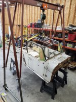
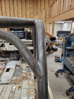
Tossed the rear axle under the rig to take a look. This is about full droop.
 

Attachments

  • 20211024_153728.jpg
    20211024_153728.jpg
    4 MB · Views: 50
  • 20211024_135109.jpg
    20211024_135109.jpg
    1.9 MB · Views: 51
  • 20211023_164330.jpg
    20211023_164330.jpg
    3.2 MB · Views: 43
  • 20211023_114620.jpg
    20211023_114620.jpg
    1.8 MB · Views: 42
  • 20211023_113902.jpg
    20211023_113902.jpg
    1.3 MB · Views: 48
I've been very happy with the ruffstuff fix-it weld washers. They add thickness around the hole, but also make the home fabrication faster - I oversize the hole on the plasma table slightly, run the die grinder a quick buzz, then weld em on. I don't have much luck drilling large holes in plate, and opening up plasma cut holes burns through drill bits like they are going out of style, so... these seem to fit the bill for me.
This works best if you remember to order them.

Some tabs to become the upper control arm mounts. 3/16" P+O plate, and because I didn't want to make two cut files, a 3/16 overlay.
 

Attachments

  • 20211026_213012.jpg
    20211026_213012.jpg
    7.8 MB · Views: 35
  • 20211026_212827.jpg
    20211026_212827.jpg
    4 MB · Views: 34
So my badass TIG welding skills could have been more patient on the weld bungs. Perhaps some hoop shrinkage from the root.

Anyhow, $8 tap from Amazon to the rescue. Straight outta China. Certainly wouldn't want to tap threads into anything with it, but worked for cleanup.
 

Attachments

  • 20211027_194732.jpg
    20211027_194732.jpg
    1.6 MB · Views: 47
  • 20211027_202755.jpg
    20211027_202755.jpg
    2.1 MB · Views: 44
Tossed the top back on, moved the b pillar spreader back about 4.5", and added a small bend to each end, to gain an extra 1/2" of head room. Re-made the b pillar bars, to line up with the newly located spreader.

Much happier with the angle and appearance from the side. Added some overhead interior bars.
 

Attachments

  • 20211030_120450.jpg
    20211030_120450.jpg
    2.1 MB · Views: 70
  • 20211030_114336.jpg
    20211030_114336.jpg
    3.7 MB · Views: 70
  • 20211028_211554.jpg
    20211028_211554.jpg
    3.7 MB · Views: 70
  • 20211028_211017.jpg
    20211028_211017.jpg
    5.3 MB · Views: 66
  • 20211028_214109.jpg
    20211028_214109.jpg
    3.8 MB · Views: 65
While fitting the new b pillars, I cut one 1/4" short. I liked the bend and the notch at the other end, and it's $7/ foot now, so I decided to save it and add some back.

With the cage partly figured out (more triangles coming after I figure out shocks in the back) I welded out what I had there, so I could use it as a pick point to pull the body.

Plenty of dirt on top of the frame, and although it used to look very stock, it looks like someone partied hard enough to demo the factory leaf spring mount. That explains the dents in the floor behind the driver seat.
 

Attachments

  • 20211031_091925.jpg
    20211031_091925.jpg
    1.9 MB · Views: 49
  • 20211106_160037.jpg
    20211106_160037.jpg
    6.7 MB · Views: 47
  • 20211106_154807.jpg
    20211106_154807.jpg
    2.3 MB · Views: 49
  • 20211106_143848.jpg
    20211106_143848.jpg
    1.8 MB · Views: 51
  • 20211106_143752.jpg
    20211106_143752.jpg
    1.7 MB · Views: 47
That upper link mount looks like a fine place for one-tool operation once the body goes back on.
 
On the subframe, did you miter the upturn? It looks like it has a 360* weld where the "bend" would be?
 
On the subframe, did you miter the upturn? It looks like it has a 360* weld where the "bend" would be?
Yup! You're seeing that right.

And, unfortunately for me there is no work like re-work. When I welded out the sub frame I put the bolts for the rear link mounts 90* to the frame. This worked in the last few cars I've worked on with 1.25 heims with misalignment reducers down to 5/8 bolts no problem, but I didn't take into account the lesser angle afforded by the summit joints. So my rear lowers took all the available joint angle and then a little flex in the steel to get the arms into the rear axle brackets with the axle flat. Any articulation would flex the materials more. So, I cut off the rear, tossed a slug in there and added another weld about 1" away, and started drilling a hole at the 16* angle from perpendicular to the frame, and then die grinding out to fit a new set of 1"x.188 4130 sleeves... maybe pics tonight.

That the corners and now but welds will be well supported.
 
Last edited:
About 30 craftsman 30 gallon air compressor cycles and enough die grinder filings to rival stripper glitter on the floor of the acropolis, and the new bolt sleeves are fit up at an acceptable angle.

Tack weld, check joint compliance in the car, then fully weld, then make the double shear support... then I'm caught back up to where I was at the middle of the day Sunday. Maybe tomorrow.
 

Attachments

  • 20211109_210519.jpg
    20211109_210519.jpg
    1.9 MB · Views: 45
  • 20211109_200057.jpg
    20211109_200057.jpg
    1.9 MB · Views: 45
More work on the sub frame...

Sometimes you have those great ideas at 10:15 as you're laying awake in bed waiting to fall asleep. This is one of those.

I'd resigned myself to having the front crossmember of the cradle welded in place and thought I might be able to get the transmission out with the body on and engine still in, but it was far from a sure thing. These simple crossmember flanges double as the double shear tabs for the front lower control arm mounts. This will allow the crossmember tube to come out, keep the suspension in the car, and make room to R+R the transmission if needed. Simple solution in the end that eluded me for far too long. The transmission pan and oil pan skid plate will be welded to the cross tube as well. More photos later and it will make more sense.

yes, a little more re-work to cut off the double shear tabs I've already welded on, but should work good.
20211113_083436.jpg
20211113_085154.jpg
20211113_085518.jpg
20211113_123105.jpg
 
I don't know if it looks like 5 hours of work to anyone else.... but here are a few more pictures of the nearly finished cradle...

Some Silicon bronze filler on the back of the nut that will not be reachable with the joint in. Made the transmission mount tube, and added the final support leg to the frame.

Some quick gussets for the rear joint double shear tabs and should be ready to weld in.

20211114_150149.jpg
20211114_150157.jpg
 
Welded the sub frame in.

Tossed the links in. Had to modify the rear cross member. Also looks like I will have to modify the body for the upper links.

20211121_091531.jpg
20211119_203448.jpg


Started working on the steering arms. Lots of staring at it. 5.5" center to center pitman arm that travels about 7-5/8" laterally. A 5.5" steering arm would net 43.7 degrees of steering. As luck would have it, the spidertrax steering arms have 5.5", 6.5", and 7.5" options. The down side is that with the tie rod in any hole on the bottom of the steering arms, there isn't room at all for a track bar that fits under the frame.

So, a significantly lower tie rod is required, but turning 43 degrees swings a lot, so 7.5" at a lower height has a good chance of not clearing the center section.

So, these might be the ticket.

20211121_193005.jpg
 
Working on steering, to figure out how much room I have for the track bar axle mount, the air bump, and the shock.

These axles are 60.5" WMS, so it's all tight with 42* of steering. The offset Barnes 4WD heims clear the center section. The extra sleeved 5/8 holes in the custom steering arms are for future assist ram mounting and to make them look symmetrical. Lots more plating to come, but had to start to confirm my assumptions. TJ box, TJ Pittman arm (5.5" center to center).

20220101_155205.jpg
20220101_162550.jpg
20220101_200106.jpg
20220101_200113.jpg
 
Quick question, what do you mean by one tool operation?
If I weld the nut to the top of the bracket, then I only need one wrench to check for tightness or remove the bolt - one tool operation. in this spot the open ended wrench barely fits between the body and frame, so it would be handy to not have e to get one up there and try to align the nut.

Of course this becomes a problem if the bolt gets bent slightly and then is a real bear to get out.
 
Lots more staring at the track bar and playing with steering today. Turns out usi g the spidertrax high steer arm bolt locations, but lower on the knuckle pulls the tie rod inboard when compared to the king pin inclination, and provides reverse ackerman. To the tune of 42* on the outside tire and 35* on the inside tire at full lock, as currently configured.

20220102_101241.jpg
20220102_100711.jpg


This happens to work out sweet as there is room to turn 42* on 315/70r17's on 4" BS TR 17" beadlocks in front of the tire before frame contact, but only 37* or so on the backside before it hits the link. I expect quite a bit of road time, and other than F1 car analogies with slip angle discussion on tires, I can't find where anyone drives on reverse ackerman in a daily driver. Some mentions of oversteer conditions.

20220102_104419.jpg


I could build straight ackerman arms, and limit the overall steering to 37* or so, but the rock crawler in me gets sad thinking that is the answer.

Any input?

20220102_104911.jpg


Mo uptravel, MO problems! Packing the track bar in here is tight. Cutting the frame would help, but it would be a really long (front to back) notch, right where the air bump needs to mount. Thinking of running a single shear track bar mount. Or I could sacrifice 1" of uptravel, would have 4.5 left, and lots more room. Have to mock up a little more and see.
20220102_171913.jpg
 
Top Back Refresh