What's new
  • Check out our new Group Buy Program! We're kicking it off with Baja Designs! $10 Flat rate shipping no matter how much you order!

Build Thread - 1978 F150 1-tons and 40s

Joined
May 24, 2020
Member Number
1298
Messages
608
Loc
OC, CA
I've made enough progress to move this into a build thread and I also have some questions/need some sanity-checks at this point so here it is.

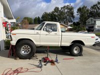
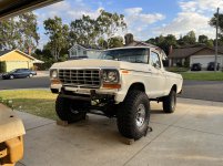
I'm starting with a 78 F150 4x4 that I've put a new motor in (400), rebuilt transmission (C6), 2" lift with 33's and overall made into a solid driver. I've been planning this build since 2015 before I even got the truck (I bought it in VA at the end of 2017). A lot of adjustments to that plan and a lot of research/learning but I finally committed this month and got started.


Parts I'm using (I'll update as I go along):

- 2005 Dana 60 out of an F350

- 2014 Sterling 10.5 with e-locker out of an F350

- WFO Radius Arms

- WFO Drag-link kit that uses the stock Ford drag-link end on the axle side with a 1-ton TRE on the pitman arm side

- RuffStuff frame outriggers

- BattleBornBrakes.com coil bucket w/shock mount -These are out boarded enough to use stock super duty coils and the stock axle coil bucket. A super duty coil lifts this set-up the lift height of the coil +1", and the lower bucket mount is higher than the Dana 44 mount by about 1".

- Skyjacker F525V 2.5" Softride Coil for a 2005 F350 4x4 - Take the above into consideration and I'm estimating about 4.5" total lift.

- BroncoAir.com adjustable shackle reversal kit (Shackle Reverse Brackets) - I have Deaver 5.5" lift springs but ran them without the 3.5" factory block. With the adjustable shackle reversal kit and no block I should be able to dial in the rear to be level with the front.


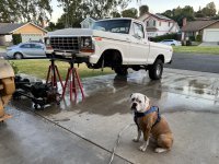
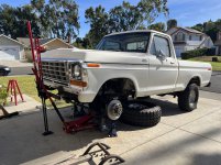
Before Tear Down
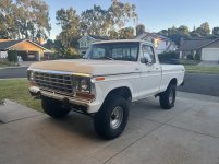
IMG_4330.jpg
 
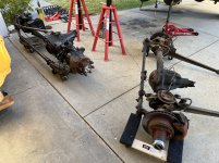
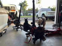
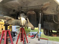
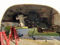
Tear Down
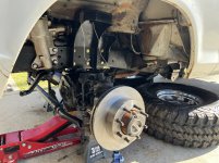
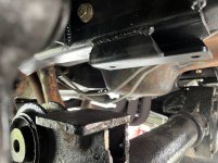
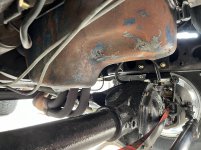
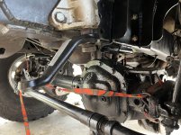
This is the easy stuff, was done in just a couple of hours. A few of the radius arm cap bolts were seized but since I plan on selling the front/rear axle, radius arms, coil springs/buckets all together I decided that wasn't my problem and wasn't about to let it slow my momentum. :laughing:

IMG_4366.jpg

IMG_4356.jpg

IMG_4364.jpg


The coil buckets and shock tower will be replaced with the Battle Born Brakes bucket/mount:

IMG_4358.jpg
 
New Parts
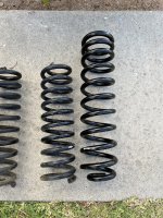
Coil Spring comparison (1-2" spring from Super Lift for a 78 F150 that I bought at BroncoGraveyard.com next to the Sky Jacker 2.5" F350 spring)

IMG_4354.jpg

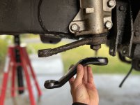
WFO sells this pitman arm that takes a 1-ton TRE and fits most saginaw steering boxes

IMG_4372.jpg

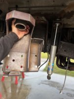
Battle Born Brakes bucket/shock tower

IMG_4370.jpg

IMG_4388.jpg
 
Last edited:
Radius Arms Part 1
I read a ton, looked at a lot of other builds, watched YouTube videos, and asked WFO about how best to choose the rear mounting location for the radius arms and how to measure the length.

What I ended up doing:

1. Put the axle on jack stands with the frame on stands as well.
2. Rotated the axle to get the caster to 5 degrees based on a plane between the balljoint and lower coil bucket.
3. Lowered the truck on to the axle to about 1" into full-bump.
4. Tacked the rear radius arm mount on the frame as close as I could to being lined up with the transfer case front output.
5. Took the measurement from center of rear radius arm mount to front radius arm mount on both sides.

This measurement worked out to 34 and 1/4 inches. I threaded the rear joint on in a way that left it half an inch of adjustment either way (longer or shorter) then welded it up and installed it. My faith in all of this was shook but as you cycle the suspension you can see the radius the arm moves in and it all becomes clear.

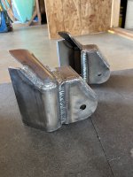
Rear mounts (welded as much on the bench as I could):

IMG_4412.jpg

IMG_4413.jpg


Lower arm mount welded up:

IMG_4471.jpg


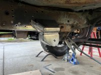
In position:

IMG_4426.jpg

IMG_4427.jpg


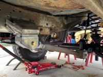
Cycling and observing clearances:

IMG_4464.jpg

IMG_4465.jpg

IMG_4466.jpg

Close to full bump:

IMG_4463.jpg

On its own weight:

IMG_4477.jpg
 
Last edited:
Analysis Paralysis

My current hurdles are:

  • How to measure for the upper radius arm link
  • Track bar length

Hopefully I can get some ideas here while I do some parallel research.


Upper Radius Arm Link

1. I've read that putting the upper link's rear mount at the axle's centerline is one person's preference. There was no explanation and I can't see a benefit to doing it.

2. I've read/seen that it also doesn't really matter all that much but a longer isosceles triangle would be stronger.

Any thoughts?


Track Bar Length

It's pretty commonly said that the track bar should be the same length and angle as the drag link for the best behavior: to avoid bump steer, and death wobble.

On a 2005+ Dana 60 the drag link attaches at the steering knuckle. It ends up being something like 50 and 1/2 inches long in my application. I can't see how to make a track bar that long in this application. If I outboard the frame side mount too much it'll get in the way of the driver's tire turning to passenger side. There's not much room on the axle side to move over.

Any ideas, clarifications? There has to be some ratio and margin for difference between the two lengths since the stock application was much shorter from factory.

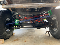
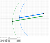
See the image below.. the track bar at these points is around 40-ish inches, and the drag link is 50 and 1/2 inches:

trackbar-and-draglink.png

Green: track bar mounts frame/axle. You can see out boarding the frame mount to make up the difference in length would cause interference.
Red: track bar
Blue: drag link
 
Make your frame side mount stout if you are going to outboard it, it will see a pretty high load.

Once you've got that and a location on the axle you can make it reasonably strong and out of the way of everything else, you've got your length. Not much else to do about it. As good as you can for matching the angle to the drag link, the better. If you end up off a little bit, meh that's fine too.

The ratio and lagging for differences is the arc they travel in from their mounts through thr range of travel. Where is the bar moving and how will that shove the link forward and back. Go ahead and draw it up with some paper or a computer and see how much it will move. The result will be likely surprisingly little.
 
I wouldnt worry about the tracbar too much. Even the OEM stuff isnt perfect and they still handle fine on the road.

Whats your plans for the fenders? I see at full bump the tire is touching the back of the fender, is it going to be a problem with fender or firewall clearance?
 
Alright, that’s what I figured about the track bar, just didn’t want to leave anything on the table if there was something I was missing.

As for the fender, it’s just the fender opening itself that contacts so far. I have a couple of ideas for that:

- open up the rear of the fender like rattle_snake did on his build which came out great and is most likely what I’ll do.

- or, it’s a bit excessive but stretch the entire opening and graft in a section from some spare fenders to make up the difference:

IMG_1520_Original.png

IMG_1521_Original.png

IMG_1522_Original.png
 
Last edited:
Loving the way it's coming out!

I was looking and the BBB bucket did come in a kit that had a provision for the track bar, if that was an option, or at least a way to copy it.
 
  • How to measure for the upper radius arm link
  • Track bar length
my 0.02

Upper arms. Pick axle caster, 4-6*. Set axle to that relative to the truck (on sloped driveway). Pick a location for back mount that won't hit anything when cycled. Leave 1" of thread showing on rod end, and you have your bar length. The rear mount location and bar length don't effect handling/anti-dive, only forward separation and frame mount.

Track bar. long as possible.
I ended up re-doing track bar mounts several times. Make axle side up high as possible, braced.
You will want a sway bar. It really needs to be designed first or at least in parallel with track bar. The outside frame mount won't work with a typical splined aftermarket type bar. To mitigate, I suggest mounting TB frame end mount directly under the frame (not in or out)


You will likely have tire to fender interference before the suspension or axle itself. So (adjustable-ish) bump stops are critical and need to be in the plan from the start. They should be out-boarded as far as possible for best result. Side to side flex will limit up travel, so bumps must be set to that, and you get what you get for vertical travel. The farther inboard, the lower the bumps have to be. Sectioning the fender will help but 40s are a big tire stuffed lock to lock

And your front drive shaft may bind u-joints up high enough for 40s, so think about limit strap placement. Grinding the yolks can help.

And that should further complicate things to prolong analysis paralysis....
 
This is a rad build, thanks for sharing :smokin:

Regarding your panhard predicament, I cannot see a path to lengthen your panhard without extensive adjustments to your steering and/or panhard brackets. A 10-inch difference between them will be noticed in the steering wheel when cruising down a road and introducing suspension travel. Factory vehicles can sneak away with it (sometimes) because the suspension travel is minimal. Any way to change the lower coil buckets to move them back so you can move the axle panhard bracket outboard more?
The issue with moving it outboard much more to compensate for that 10" is that it would put the mount into the tire when turning.

With rattle_snake 's input in consideration I think I'll be re-doing this again some time shortly after getting this truck on the road.

I'm on a bit of a timeline to at least get this truck rolling (well enough so it can be pulled onto a flatbed) as I'll be moving at some point early this year (hopefully into a house with a flat area to work on my stuff).
 
Went back to BattleBornBrakes.com to look at how he handled track bar mounts in his swap kit... if I end up having big enough issues with the track bar I could get a different steering box that mounts on the inside of the frame (super duty box) to shorten up the drag link bringing the length ratio in closer between the drag link and track bar.

Doing that could let me move the frame side track bar mount under the frame rail as rattle_snake suggested which may clear things up for a sway bar (I haven't made it far enough to think about the sway bar at all). Another reason I know I'll do this twice is because I eventually want to go to high-steer arms which will change the angle on the drag-link a bit.

Had to do some work on the gf's 67 Bronco but now I can get back to focusing on the F150. Need new jack stands because the axle sits too high with the 40's now :smokin:.
 
Nothing wrong with going in stages. Life tends to get in the way of a build.

Shortening links usually won't help. Yes you will want a high steer arm in the end if you want it done right.


As much of an analytical asshole as I am, I could not get the steering/trac bar math to predict road manners. In the end all you care about is horizontal shift vs vertical movement (some multiplier value) of both knuckle and axle housing. In the real world nothing will be parallel or equal, so the ratio of the two multipliers will not match and will accumulate horizontal error over vertical travel, aka bump steer. To mitigate, have multiple holes to choose from. Mount hole being only 1/2" off vertically can have terrible bump steer.
 
I had good luck cutting dent side fenders right at the beginning of the flare-out all all 4 corners. Use nibblers for a cleaner smooth cut. then you can slightly open the rear portion of the opening or as needed and its barely noticeable.

Sorry at work so this is the only picture I have, this was 39.5's with right at 6" lift. Later ran 44's with narrower wheels, little less lift, axle forward 1.5" and more travel with only slight trimming required.

IMG_6163.JPG
 
Doesn’t seem like much I but finished measuring/cutting/welding the upper radius arm link and finished building the radius arms.

I still have more cutting and grinding to do on the axle’s stock track bar mount then I can build the track bar, the drag link, and make some brake lines. That would let me turn the truck around in the driveway so I can start on the rear.

The Bronco stole my free time away for about a week but focus is back on the truck.
working is the easy part, it's the figuring out what/how/when/why you are doing a thing that's the hard part :laughing:
 
working is the easy part, it's the figuring out what/how/when/why you are doing a thing that's the hard part :laughing:
Seriously. I thought I had every step figured out as I’ve been thinking about/planning this build for years but there was plenty more to think on that I hadn’t considered. I feel like the radius arms were definitely the trickiest thing to tackle.
 
Make your frame side mount stout if you are going to outboard it, it will see a pretty high load.

Once you've got that and a location on the axle you can make it reasonably strong and out of the way of everything else, you've got your length. Not much else to do about it. As good as you can for matching the angle to the drag link, the better. If you end up off a little bit, meh that's fine too.

The ratio and lagging for differences is the arc they travel in from their mounts through thr range of travel. Where is the bar moving and how will that shove the link forward and back. Go ahead and draw it up with some paper or a computer and see how much it will move. The result will be likely surprisingly little.

Whipped up a little interactive Javascript canvas to see what it would look like if I just used the store-bought mounts and didn't do anything too crazy (will probably make this available online later once I clean it up a bit in case anyone is interested):

Screenshot 2024-01-17 at 16.21.37.png

I'm going to weld up the drag link tomorrow so I know what my angle is, and then some time this week finish grinding off the old mount off the axle. I'll most likely draw something up in CAD and send it out to be cut so I can get more offset from the frame and sneak a little bit more length.
 
The arc diagram above is a great way to see the difference in horizontal positions through the travel. Typically the suspension is not going to go from full bump to full droop at speed. More like 1/2 that, looks like an inch or so that knuckle will turn. 10* is steep. It should meet your goal of getting it driving.
 
The arc diagram above is a great way to see the difference in horizontal positions through the travel. Typically the suspension is not going to go from full bump to full droop at speed. More like 1/2 that, looks like an inch or so that knuckle will turn. 10* is steep. It should meet your goal of getting it driving.
In my little program 10 pixels = 1 inch and one square in the grid is 10x10 pixels. I don't have the exact angle yet as I didn't get around to building/mounting the drag link yesterday.

I was hoping it would be good enough for road-duty to get me started. Those lengths are pretty much the worst-case-scenario and I should be able to get them within 5" of each other if I make my own frame bracket.
 
Finished grinding the track bar mount off the axle, got the drag link welded up, pitman arm installed.

I have a CAD model drawn up of a track bar frame bracket but want to retake measurements after I weld the axle bracket on. I jacked up the front and turned the wheel full lock to see how far out the track bar bracket can extend from the frame.. basically my track bar’s max width will be 44-ish” and the draglink is 51”. Still looks like minimal deflection so I’ll run it and see how it goes.

Here’s a pic of the wheels turned full lock with radius arms that go straight back (no bend in the arms) from a 2005+ Dana 60 and 40” tires:

IMG_4665.jpeg

I’m surprised and pleased with the result.

Looking forward to see what you come up with overall on the track bar. Have a "street" 79 bronco on 35's that is a pretty good driver, but never hurts to upgrade if possible.
 
Great progress. Glad the tires clear at lock, perfect. Did you choose the out rigger brackets to keep the arms parallel with no angle at the axle side bushings?

I had to bend radius arms as my Ballistic brackets put tube about 4" closer to the knuckle. Later on this made axle side RA bracket perfect spot for bump stop pad.

Yeah, I wanted to do this in the most straightforward way possible (literally & figuratively).

Dying to get this thing turned around in my driveway and start on the rear. I can't count how many times people passing by ask me if if I'm going to "put big tires on the back too."
 
Last edited:
Top Back Refresh