What's new

'56 willys truck

from Alcurtice: Hey Chris, I'm installing a 3 link front suspension system on my 57 Willy's truck and I am running into some issues. How did you set up yours? If I put the lower links under the frame it appears they would be open to some rock crushing. My drive line is 48" long so I've been told I need to keep the lower link the same length as my drive line. this puts the lower link mounts way back in harms way if mounted under the frame. Inside the frame is not an option because of how the frame tapers in to the front and gets in the way. So I put mine tacked to the outside of the frame and up but this could cause problems with tire clearance. I would also like to see how you set up your third link. I hope all is well with you - you've been quiet lately. Maybe your having too much fun wheelin now that the weather is good.
yH5BAEAAAAALAAAAAABAAEAAAIBRAA7


from me: alcurtice--my lower mounts are welded to the inside of the frame to keep them as high as possible and away from the tires. If I remember correctly mine still stick below the frame and I think it's about 1 1/2". The length I'm thinking was like 52" center to center of bolt at the heim, but maybe they're 55". They're not as long as driveshaft if I was to measure from t-case to axle yoke and I don't know that dimension, but the NorthWestFab doubler pushes it back 8-9" I believe. I may have to do a carrier bearing. As for the bottom links being as long as the driveshaft I think it's a good idea to try and keep them close and close to the same angle if you can, but as much as I've read about doing these everyone usually says do the best you can.

I'll take some pics and unfortunately the jeep hasn't seen much progress, because I've been working on my brother's 53 cj3a, cousin's house, building a deck for my brother at his son's mother's house and it's been raining a ton here, not to mention my regular job.
yH5BAEAAAAALAAAAAABAAEAAAIBRAA7


front lower arms are 47" long and upper arm is 40-40 ½" long--center of heim to center of heim

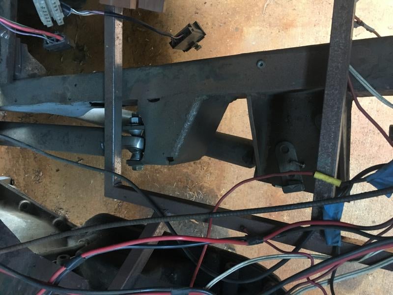
frame mount for front lowers are inboard from inside side of frame 4 ½" to the center of the arm--I still need to tie them together using some tube going across the top of the tranny, because of them being 4 ½" from the inside of the frame

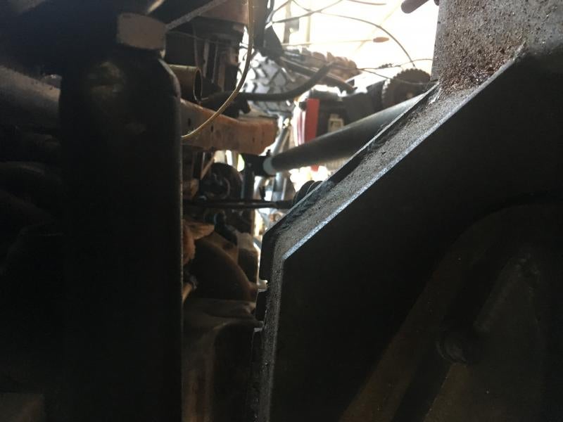
lower arm frame mount measures 1 ½" below the frame to the very bottom of the mount--bolt hole is about ½" below frame--I wanted it higher, but it just didn't give me the separation distance between lower and upper arm frame mounts.

the lower arm axle mounts are pulled from hooking the inside of the "C" to center--see pic for dimension

the upper arm axle mount on the passenger side is 14 ½" from hooking inside the "C" toward the pumpkin

the top of the upper arm frame bracket is aligned with the top of the frame

1979 ford dana 60 hi-pinion king pin--stock width
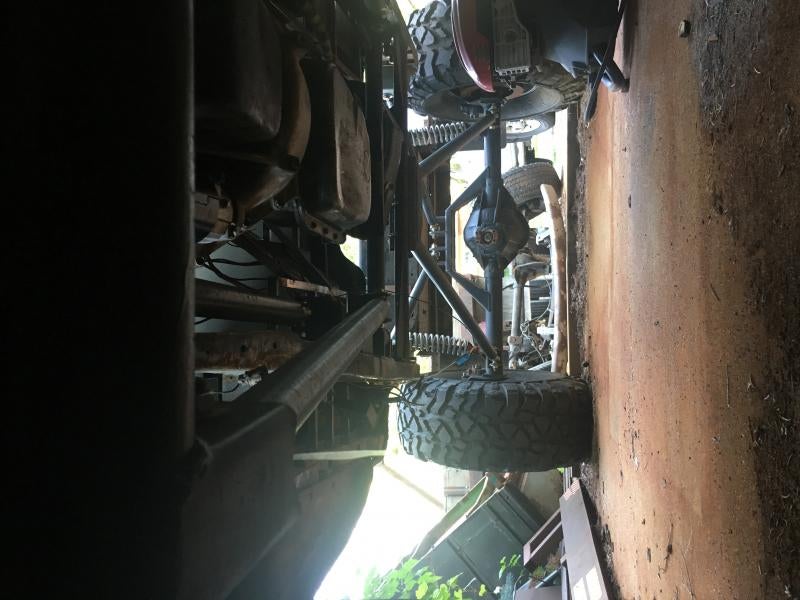
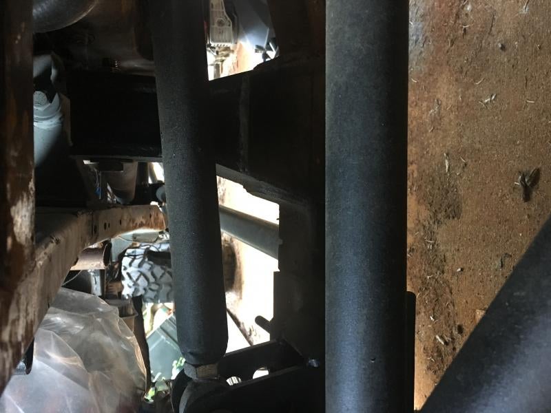
img_6216-jpg.2885576


img_6217-jpg.2885578

img_6220-jpg.2885582

img_6221-jpg.2885584
 
3 link calculator you can download

4x4 Excel Spresheets

hardest part about the using the calculator is interpreting what x, y & z are, but if you move your mouse over the box under x, y or z it tells you what you need to measure.

this isn't the exact way to do it, but you could measure from the centerline of the axle back to your lower arm frame mount--hold tape measure level then take that measurement x .75. So if your lower arm frame mount to axle center line measurement is 48" x .75 =36" and then from center line of axle back 36" is where you mount your upper arm frame mount. So it's not .75 of the lower arm length per se, although I'd bet lots of guys do use that for their suspension arms lengths. I try to mount my upper arm axle mount as near to perfect vertical as possible, because tilting it one way or the other means you have to add to the arm or shorten the arm.

you can read a lot and be just as confused as when you first started reading. I had found a nice drawing showing all the measurements, but now I can't find it, but I'll look for it when I have time, but I'm headed out the door here shortly, so it could be tomorrow.

hope this helps and if Mieser and a couple of others chip in they know this stuff inside and out---you can also search through my '48 build and the info is in there I'm pretty sure....


found this although it's stating 70% of the lower arm length where the lower arm isn't measured as level--I thought it was a level measurement, but the difference between level and not level is probably ½" or so, so not a big deal and 70% vs 75% again not a big difference.

from Alcurtice: I read somewhere that in the link calculator, it is best if the Anti-Squat percentage is somewhere between 50 and 100%. I am at 122%. So does that mean I'm gonna hate this thing?

from me: Beauty is in the eye of the beholder, so to be honest who knows if you will hate it or not. You will only know after you've driven it under many different situations and as always a lot of our rigs are really, really good at some things, good at most and maybe have a couple of things that require more concentration. My guess is no you won't hate it and will learn to drive around any issues that arrive from 122% anti-squat, if indeed there's an issue. I've not read everything there is about anti-squat, but what I have read seems that it's the steep steep climbs where this comes into play. There's guys who say keep it under a 100% and others that say keep it between 75%-125%, so this proves the point that it really depends on what kind of trails you run and how you like your rig to react. Also there's so many guys that just build what they can due to packaging restraints and are quite happy. Build it, drive it and enjoy it for what it is.

Mini update--installed the front bump air bumps and have decided to redo the back of my frame/shock hoops with a big aggressive "C" notch that should mean clearance for larger meats in the future and will allow me to turn my coilovers around to get the hose pointing to the outside vs inside the bed which was going to take up bed space. I'll post some pics when I get more done. The frame between the C notch and tube shock hoop will be removed.

Feels good to get back on it, well until I started making 16 gussets and drilling 64 1.5" holes in said gussets for the frame alterations.

Still a long ways to go though and helping my brother on things will mean progress won't be fast, but at least I'm back on it....

56-willys-frame-mod-underway-jpg.2928398

from TimCubed: Poly Performance had 90 deg fittings for the shocks $19.95 each. I have to buy 4 myself

from me: thanks for that info--I'll have to look into those even though I'm committed to this new design. I'll have another frame tie in that will run inside the lower frame rail and shocks so that I can mount my bump cans and add help to the ultra C notch!! The C notch will also help me with me attachment of the fenders that will need to be stretched and inside the bed wheel wells. Plus it's what I have available for material.


The bumper has been removed along with the fuel tank skid that I had put in last year, because I was going to put the fuel tank back there, but I doubt that happens now. The back of the frame will be cut off and 2” x 4” x ¼” tube steel in it’s place is my thinking now, still need to give this some thought, and I may hack up the old bumper and incorporate the parts I want into the new set up. So if I can keep everything even with the bottom of frame I will have gained 8” of extra ground clearance at the bumper and shortened it about 10”-12”.

As for the bed right now (could change my mind after I look at it for awhile) I’m planning on notching it around the new frame configuration, building some wheel wells inside the tub. As for the fenders I’m not sure if I’ll build new(leaning this way) from 1 ¾” x .125 DOM tube and some steel plate or cut the old ones in ½, stretch them and add the DOM tube and maybe some steel plate covering them. I’m also thinking of sleeving the upper part of the bed sides with some DOM to give them some extra beef, but that will be down the road when I can give it some more thought and see if it makes sense. Still have to figure out if I’m putting a headache rack/roll bar in the bed or not.
 
Small amount of progress.. bumper is tacked on and I’m not sure the sides will remain or not— will make the decision once I get the bed on. My friend Dennis, from Kenya, is here visiting so I have some assistance. We are working toward the bed support & bumpstop structure and bed mods to get it set on there.

cde55517-5e06-437d-a912-858e01fe17de_1557858298238-jpg.2930918

039bd8cd-8e07-49f3-8a3e-b2f9f737be7b_1557858317708-jpg.2930920

324b2003-515a-4d22-9fee-f55f462f341f_1557858360597-jpg.2930922


set the bed on it for the first time in about 2 yrs, but it started to rain so it was done for the day---have to redo at least one mount on the passenger side and may redo 1 more on the passenger an 1 on the drivers side..but regardless nice to see it on there and now I can start to figure out how I want to finish it up.

I forgot it didn't have the W or Willys insignia on the tailgate, so that bummed me out. I'll be looking to do something to alter that down the road.

img_8024-jpg.2931358

img_8025-jpg.2931360
 
some more bed work...from notching the bed out I had to put back in the bed supports, so I cut the spot welds where the bed side was welded to the bottom support. Then a couple of small notches to allow the support to slide in and then welded the bed to the support. I'm not sure ifI'm using the old bed side for the wheel well or not. Also patched the bed and welded the bed seam up the middle as it was separating.
img_8119-jpg.2932884

img_8120-jpg.2932886

img_8144-jpg.2932888

img_8145-jpg.2932890
 
been chugging along on exhaust when I can get time to work on the ol' gal. Had to massage the down pipe off the passenger side exhaust manifold to miss the upper 3 link at full stuff and then I had to order one of those 3 bolt flanges that allow you to clamp the down pipe to the exhaust manifold and that took me cancelling the order at O'Reillys and getting it from AutoZone. No biggie, but of course this weekend when I go to use it it's to small so out with the grinder to enlarge it to fit around the pipe and 4.5hrs later with the die grinder we achieved success. Exactly the amount of time I figured it would take. NOT!!!!! Crazy, crazy, crazy how long some things take.

Then next was to figure out a mount for the front driveshaft carrier bearing I will need to use and a removable cross-member for the skid plate. And it was 98* out with no breeze until the end of the day. Lord that was a fun day. Progress is slower than a two legged turtle. Oh well, if you want to play you have to pay one way or another.

Now to figure out what carrier bearing to use. Do I do like I did for my '48 and use a dodge 2500 rear driveshaft & carrier bearing or chev or ford and modify it, but that will mean a trip to pick and pull or order parts from one of the builders=mega$$$ or order stuff from like denny's driveshaft or such(less mega $$$)?? Decisions, decisions, decisions....


Been slowly making the carrier bearing mount and skid plate mounts and skid plates--last one is on the paint pile. Received my Red Neck Ram kit from West Texas Offroad, so now I've got a few things to work on that are all #1's on the list!!!!


Well I got off the couch(more like I've finally had some "me"
time and the weather is cooperating) and for the last week I've jumped back on the project. I mounted the Red Neck Ram, steering linkage to the steering box, winch mounting and a lot of staring!!

So a couple of things I'm fighting at the moment. One, it's best if one does the steering linkage to the steering box to check the swing rotation of the pitman arm using the steering wheel to turn the box!! I knew I had turned the input shaft to the steering box with some vice grips to check the swing and box center, and I did it more than once and on a few different days, but evidently I didn't get it turned all the way left and right or somehow I set the center wrong because for some reason I can make the box rotate more with the steering wheel now vs with the vice grips. This little malady came to light when when turning to the right the drivers side knuckle wouldn't hit the stop and when turning the left the passenger side would hit the stop. So now I'm in the throws of adjusting the tie rod, drag link, steering box center and probably having to cut off the tie rod ram mount and redoing it. Will keep you posted on what I finally figure out I did wrong.

Concerning the notching of the frame it's a matter of me not mounting the box low enough on the frame or you could add spacers to the frame to not have to notch. I didn't want to lower the box more originally and I couldn't use spacers or I'd get interference with the radiator, so it's just one of those things you have to do depending on where you want your box. Now with that being said I did think I was clear of the frame due to earlier attempts at rotating the pitman arm 20-30 times with the vice grips. I think earlier I mentioned I had to notch the front cross-member also, but this wasn't as bad as I didn't have anything connected steering wise to the box, but now it's all connected and it was a bit tricky to get the grinder in there to notch it, but I got it and now I have to plate it back together.

This has really made me appreciate full hydro set-up I had on my '48 willys, but I'll get it figured out and it's kind of an interesting puzzle on one hand, but still it would be nice to not have to undo a bunch of stuff!!

I will also probably have to do Ford Facists anti tie rod spin set up or something like it. I'll keep you posted on what I do.


I've relegated the issue to the box not being centered, because it hit the frame rail and I could never see that when turning the steering input myself. This is one time when you really need another hand to see pitman arm swing while someone else turns the input to the steering box if you are trying to keep things packaged tight. So in the end I have to redo my ram mount on the tie rod and I believe I will also have to move my antirock sway bar axle mounts since my tie rod will now probably smack them, but I need to get the ram reconnected to check that out. I'll also need to double check my toe in.


Steering ram in, hoses ran(maybe--need to cycle suspension and move wheels back and forth before calling it good)--right now it looks like I don't have to do the FordFacist anti-tierod spin set up--column to steering box linkage done--still need to add a strap to the top of the ¾" heim to pretty that up, power steering pump hoses to steering gear box done & all that's left is power steering fluid and of course test it all out when I get the truck running.

So I went to a hydraulic shop and had them cut the factory pressure hose steel pipe at the pump side and had them crimp on compression fitting and bought some steel straight and 90* -06an fittings and hi-pressure hose and made my own hoses for both the pressure hose and return hose. For the return hose at the pump I used a barb to -06an to transition from the pump to hi-pressure hose. This way at the steering gear box fittings and hoses match on both the pressure hose and return hose.

I'll take pics and add them later.
 
Earlier I had said I was going to use a two piece drive shaft for the front and I built a mount for it, but after stopping by the driveshaft shop last week and looking at carrier bearings and taking some measurements, I decided to remove the mount and modify my skid plate sub frame in hopes I can run a one piece drive shaft. I'm still kicking around making my own front drive shaft, but we shall see if I can get by with the yoke at the t-case or if I have to go flange and double cardan set up just to add some length to help get by the tranny mount. If I have to go double cardan then it's driveshaft shop time I think.

For some reason my front coil-overs decided to leak down, so now I've got to get those rebuilt!!

Flanges showed up for both front and rear of the NP205, but now I need to buy a 1 5/16" socket to remove the yokes and put the flanges on---can't believe I don't have this socket, but I don't...

I threw in one of my cadillac seats to see how it fit and they are to big, damn. They are 10" longer in the seat area vs master crafts and probably corbeaus from back of wall to the front of the seat cushion. So now I will need to sell my cadillac seats and probably buy some master crafts.

Set the JB Customs triple stick shifter in to see where I can place it...I'm going to need the seats to figure it out where to place it and the 4l80e shifter and how to finalize the console design.


bought a socket--took 3 different auto parts store to find it, but lucky for me I have 3 different stores right next to each other, so I just started at one and walked to each one --Napa for the win....

master craft nomad seats are ordered and should be here by next monday, but I'm hoping they come sooner.

Weather sucked this weekend so I didn't get much done--3" of snow and then it started melting and dripping all over the rig on Saturday and then it was cold with the wind blowing yesterday so I stayed inside. Today is to be high 40's so I hope to get back on it after work.


seats are to arrive today
yH5BAEAAAAALAAAAAABAAEAAAIBRAA7


live and learn lesson 1 zillion plus--I thought I'd left enough clearance for the flange on the rear t-case output, but I didn't, so now I'm hacking and whacking out metal and welding in new pieces...this isn't fun because I don't want to take out the cross member that holds the t-case and rear links. So a 1350/1410 flange for a NP205 measures 5" in diameter and I allowed for a 4 1/2" flange. Not sure where I got that dimension from, but I did and now it's loads of fun time. And it's raining and it's going to get colder, so triple the not fun factor if I decide to continue my attack to remedy the issue.

I swear sometime soon my posts will have good things they just have to, don't they?


The modification to clearance rear t-case flange is complete and checked and I measured for the driveshaft. The one I just bought is 2-3" too long, so I'll take it to the shop and have them shorten it or have them build me a new one and I'll use this one for the front once I get those dimensions.

Set the new driver's seat in and jumped in and I have to shorten the steering column again as somehow my measurements of where to place it and the previous shortening was incorrect. Oh well under the knife it goes again, but I'm going to lose the electrical connection for the gear selector(was an auto column shift) at the base of the column. I'm hoping that won't screw with the computers, but if it does then reverse valve body manual shift will/should sort that out. Hell I should just buy it now, because my luck will be that I will have to do it anyway!! I'll have to modify either the dash mount or mount on the column to push it away from the seat.


Column shortened--tried to relocate the dimmer switch connection on the column, but it's not working like it should, so I may have to use the old foot switch if I can't make it work, so I've got a little more thinking to do to see if I can get the activation rod to work like it should. I basically unbolted the connector from the column and bent the bolt hole part of the bracket 90* instead of the 10* bend it had. This allowed me to re-position the connector more on top of the column vs on the side. The rod that goes from the dimmer/blinker switch is 1/8" and basically straight, except for a little kick up at the end where it enters into the connector, needed to be modded to get to the connectors new location. I cut a piece of rod off another steering column that's been stripped of most of the wiring and bent it into a "S" shape and welded it to the rod on the column and reinforced it with a gusset, but like I said it just doesn't work like it should. There's to much flex in the 1/8" rod, so I may have to weld in a guide or two to keep the rod from flexing, we shall see.

So now to the unfortunate part I nicked the wiring on the column harness as I was trying to gingerly cut away the plastic shroud that's on the column. This shroud is behind/below the blinker/dimmer shroud on the column. It's just a beauty piece to hide wiring and the rod mentioned above. The dang wires were right up against the shroud and I nicked every one of them. So now I have to see if I nicked the wiring or just the sheathing to see what I have to do to repair. Hopefully it's just some shrink tube on each wire(about 15-20 of them). On one hand it's pain but on the other hand it's not that big of a deal and that's because the connectors for the wiring are disintegrating, so I have to cut each wire anyway to reconnect them either with a new or used connector or splice them together individual connectors. Either way each wire has to be pulled out of the connector and separated and this will allow me to slip on a piece of shrink tube.

Now with that all being said I do have the other column that's been stripped of most of the wiring(only blinkers and maybe the horn wiring remain), so I could shorten it and install it vs monkeying with the above column, but I just wonder what issues with the computer I may have by doing this??

I'll take some pics tonight before I start on another episode of "how the steering column turns" to give you guys an idea of what's up.

so that rod doesn't like to be welded to, so I had to spot weld the "S" piece on and the gusset--it doesn't work, so I took it off and will use the floor dimmer switch, but I will look at it again tonight to see if I can move the switch up on the column, but I think it will be to big or I won't be able to get to it to plug the harness in.

I had to notch the shroud to fix the cut wires--luckily it was only 3 that were cut through. I used some of that shrink-tube with the solder inside of it--I ended up wrapping each wire with electricians tape and then I bundled it with some more tape. The shrink tube with solder is a cool idea, but I'm not 100% sold on it as to heat the solder enough to melt the plastic melted also. I was using a heat gun, so maybe that's not what I should use, plus it was slightly congested area to be doing such.

Steering column mount completed and it works.
 
tonight I'll mount the steering column and toss the seat on some wood and see if I'm in the range--probably should've done that before I fully welded the mount up, but what the heck I thrive on re-doing everything!!!

Next thing will be will I really want a tilt column, which I have, but it will need to go under the knife too.

To shorten a column, at least on a '92 chevy pickup column, the following needs to be done: pics later and even then I didn't take some that I should've. Column was an auto shift on tree.

You have the following parts:

spring clip that holds the retainer cap onto the column
retainer cap
bearing(plastic with rubber seal)
spring(may or may not be there)
thin plastic washer
inner shift tube(this is collapsible, so you don't want to cut this section and it steps up in 3 different diameters from steering wheel side to the end of the column)
Outer column
Steering shaft

Measure how long your column needs to be and subtract that from your column length to get the dimension you need to cut out of all the pieces.

Say your column is 38" and you need it to be 32" so 6" is what length you will be removing from the shaft, shift tube and column.

So you pop the spring clip off and then the retainer cap slides off, remove the bearing & spring if it has one and pull out the inner shift tube. I'd mark the the column in relation to the shift tube so you know how to orient it when you slide it back in later. It's not a must if you are ditching the column shift, but there are two tabs or bump outs on the steering wheel side that slide into the column shifter and you can be off 180* if you don't mark it or make a note of how it was installed.

Then cut the outer column off. You have to take into account that you need to cut the column past your steering shaft cuts, because you need to weld the steering shaft, so this column cut will be closest to the steering wheel side as far as you can or need to.

Cut steering shaft and cut off the dimension(6" in this example) and slug it(inside). If it's solid you will have to check the inner diameter of the shift tube to see if you have room to sleeve the outside. I also plug welded mine. Try and keep it straight!!

Now cut the shifter tube and remove what you need(6" in the example). This stuff is thin, and you can't slug it because it won't slip down the steering shaft, so you might be able to add some tabs to the exterior. Again check inner diameter of column vs shift tube outside diameter to see if you can do this.

Then remove 6" per the example(your dimension may be differet) from the column and weld it back on. Again this is thin so tabs may be needed. Reassemble in reverse order.

Also you can cut off the linkage arm at the end of the shift tube--leave about a 1/2" of it sticking off the shift tube--if you aren't going to use it. You need the shift tube since it's the seat also for the bearing, so you can't just toss it out.

Also you may lose the electrical switch for the column shift, which I think or hope is only for the instrument panel to note which gear you are in. It may have the neutral safety switch as part of this connector, so that's more tech that I have not figured out and I may not need to do it. Also the column headlight dimmer switch will need to be modded(more tech that I may or may not have in the future) or removed and you install a floor mounted switch. All of the above will depend on what vehicle make and year, vehicle motor and tranny and column you are using. I also had to cut the main harness clip to get my column down to the length I needed it, so you may have to wiring mods to keep things up out of the way. I have to ditch some of the connection on mine because the connectors are disintergrating like I stated an earlier post.

Good luck...

steering-column-spring-clip-1-jpg.2969770

steering-column-bearing-retainer-cap-3-jpg.2969772

steering-column-bearing-4-jpg.2969774

steering-column-shaft-5-jpg.2969776

steering-column-shift-tube-6-jpg.2969778
 
outer column
main electrical connector clip
slot where shift indicator switch goes
shortened column with D shaft next to stock column with splined shaft

steering-column-7-jpg.2969780

steering-column-electrical-connector-clip-8-jpg.2969782

steeering-column-shift-indicator-electrical-connector-slot-jpg.2969784

shortened-steering-column-with-d-shaft-vs-stock-column-with-splined-shaft-jpg.2969786

the saga of how the steering column turns part 54---after shortening and installing the steering wheel sits low. It will work, but I feel like I'm sitting to low in the seat and want the seat to be higher which then makes the steering wheel to close to my legs, so it looks like I'll be shortening my tilt column and using that or seeing if that will help. Or I raise the column which then causes me to rethink my dash layout. I had originally thought I'd re-use the '92 chevy instrument panel to get it wired up and running and even slapped together something that would make it fit in the glove box above the steering column, but if I move the steering column up then I'll have to do something different.(it was moved up by a previous owner, but I wanted to use that glove compartment for the gauges and so I moved it back down)

I tore into the dash wiring removing some old wires(speaker wires for power wires) and then I unbolted all the stock gauges to check the wiring and as you all know that was PHUN!!! I now need to figure out how to test them to see if they work and do I resuse them or not. A man needs options!! If I remember correctly one or two of them did work, but I don't recall which ones now. Curious thing they all are electronic and not mechanical. I would've thought the oil pressure would've been mechanical. And let's say I want to use them. How do I tie them into the electrical of the '92 chevy, so that the computer is happy? Maybe the computer isn't tied into the gauges, but my guess is that it is for the idiot lights to function. I got my work cut out for me on researching, testing and then moving forward with some sort of action plan. New dash to overlay the existing with new gauges? Who knows.....

I know 49Willys_Mogon had someone mod his gauges to solid state, but I couldn't find it in his thread. Hopefully he's still floating around and will let me know, so that I can look into that. I could've sworn it was in his thread.
 
Ok, I decided to just buy an Intellitronix DP10002R gauge set and a GPS speedo sender for it, so either I've screwed my self with wiring or it will be fine. I did this because my made up '92 chevy gauges don't fit behind the steering wheel like I wanted and right now I'm not sure I want to hack up the dash to make it fit, because I don't really like the look of the gauges. We shall see how this all comes together.

Now back to the steering saga, I knew you guys have been waiting impatiently for the next round of bufoonism's by Chris. Well the '92 shortened column has been kicked to the bench and the tilt column of some unknown year and make, although I think it's a chevy is in the game. This is because the tilt column allows the steering wheel to be higher in the cab and it's much more comfortable layout. But with this comes a wiring headache as there's none of the wiring connectors on the column. They were removed by the previous owner and all that's there is two flashers tied into the column wiring for the turn signals and emergency flasher. Even the key switch and all the wiring is gone. Also this column since it's a tilt column is assembled differently so shortening it may prove to be a bit of a headache, but I'm going to try and not shorten it with some creative shaft routing, but it may not work. This weekend I hope to finalize once and for all this steering issue.

Wiring, holy bat guana is there a ton of dash wiring and connectors in a '92 chevy k2500. I kept it all, the A/C, heater, radio, lighting, instrument cluster, cig lighter and column(dimmer, windshield wipers, windshield washer, turn signals, tranny selector, emergency flashers, ignition) and I have to be forgetting something because it looks like I have enough connectors to power a small city. bummer for me is that my permanent marker pen didn't turn out to be so permanent on blue tape, so now a lot of the wires are unknown to where they hooked to. So yea I've got a lot of deciphering to do, ugh!!! Now this leads to another issue.

Originally when we bought this thing it had a 307 in it and I bought a FAST efi set up that I was going to swap in it, but then I traded that motor(good thing as it blew up later) for my brother's '92 chevy motor, tranny, t-case, steering column, steering box, wiring harness, brake pedal, brake booster and master cylinder and what ever else I could grab. Then I decided I would just use all of its wiring and get it back up and running and then see if it made sense to swap on the FAST EFI, but now I'm wondering if I just shit can the entire '92 TBI and wiring and use a Painless set up(I think I have a kit) and the FAST EFI. I think this will force me to buy a reverse manual valve body, so that I rid myself of the tranny wiring, because I don't think I can wire around it unless I get a stand alone controller.

What do you guys think? I don't mind manual shifting the 4L80E as I manual shifted my dodge for years. Oh well time to pull the FAST out of the box again and painless set up and read the instructions. I think the FAST EFI/Painless set up would be easier to integrate the Intellitronix gauge pod also vs the '92 chevy wiring.

oh boy, can't wait!!!!:laughing::laughing:


tilt column is in, I just need to make couple of gussets for the heim joint support. I didn't shorten this column, but I did hack out some of the shroud behind the steering wheel, that way the mount I made for the shortened column would work by just drilling new mounting holes. I wanted to do that so that just in case the tilt column turned out to not work I wouldn't have to make a new column mount. This tilt column had an aluminum shroud vs the plastic one on the '92 column, and that aluminum piece is tied to the shifter by being welded on, so I don't think you could hack more out of it if I wanted. I of course had to relocate the heim support and that was no fun cutting it off!! I have to start just tacking stuff in instead of believing I've completed the task 100%. Maybe one day I'll do that!!

You are probably asking why I didn't shorten this column but the other one I did, well that was because the u-joint on the "D" style steering column shaft wouldn't rotate at the angle it ended at when it was full length, but the splined column shaft u-joint does. Funny how that worked out.

'92 chevy wiring is in the throws of being removed and the FAST EFI and painless wiring will be going in. Rain and hail stopped me today for now, so I decided to come check on all you guys to see what's going on and it's good to see guys back to working on their stuff and some new builds going on.

wiring removed--TBI removed, dizzy out and new FAST dizzy ordered(nice surprise #1), intake manifold out and the one chevy manifold I have doesn't fit these heads--my luck, so new Summit racing intake ordered(nice surprise #2). The center bolts are different. I had no idea about the dizzy and intake, but I've been out of the chevy game for sometime, so now I'm learning new stuff, always fun when you think you are going to get "X" done and then mother-in-law bad luck steps up and kicks you right where it hurts!! At least the top of the engine is will be cleaner!!


Intake manifold and dizzy showed up yesterday, but it started to rain and the temp was dropping fast, so I pushed stuff around in the garage to start making way to maybe bend some tube for the roll cage.


intake manny in, dizzy set, FAST throttle body bolted in--I put a spacer under it and I have no idea if that will help with anything, so we shall see. Still needs all the wiring and plumbing to be done.

Interesting note concerning heater hoses on '92 chebby 5.7 motors, the return heater hose went to the radiatior , so I'll have to fab up a tee to get it plumbed in, cuz there's no other place to plumb it in.

I started to work on the PAINLESS WIRING, but then said screw this, because it was getting dark and I was trying to adapt fit it into an existing hole I had cut and it was giving me fits. I'm going to make a plate with the correct cut outs and then fasten that to the cowl.

So yesterday was floor pan day and I got most of it done, but still have the tunnel to complete, because I'm unsure of the design of how I want to position some switches, shifters and what not, so I may start on the roll cage, so that I can position the seats to see what I want/can do.
 
I got the floorboards in and most of the tunnel done, but leaving off the top and 2 small side pieces that are under the driver's seat just in case I do a bit of remodeling there. The top is off because I've not determined the final design and I'm thinking I may run a conduit or a u channel for a future wiring chase and I'd want to weld that in now.

Pics of a frankenstein floor board system might lead all you guys to abandon your clean work, so there's none here yet. Once I get the roll cage in and center console then I'll throw a pic or two up.


Roll Cage has commenced: so I made a cardboard template that went from floor to ceiling and dash("A" pillar) to back wall("B" pillar) and then traced the door opening and then dashed in where I wanted the hoop to sit. Then I took my 90* tube bend template and marked out where the bends would start(in my case I align my bend marks at the beginning of my 180* die). I took some dimensions & got the bend angles also. I then added up the dimensions and came up with a length of 124", which I figured was probably more than I needed, but to be sure I cut a piece of the DOM 130" to start. Starting at the "A" pillar and working back to the "B" pillar I laid out my first bend mark at 27" and commenced to bend 18*(162*). My next dimension to follow the windshield angle was 23 3/4" from my first bend mark to the next bend mark and then made a bend at 67*(113*) and then the last bend I measured 21 3/4" from the previous bend mark to the last bend mark and proceed making a 90* bend.

So of course it's long, so I measured from floor to ceiling at the "B" pillar and ended up cutting off 9 5/8" at the "B" pillar leg and measured at the "A" pillar and cut 1" off the "A" pillar leg. I had to do this a couple of times and ended up cutting a total of 10 3/4" off the "B" pillar leg and 2 3/4" off the "A" pillar. This means a tube 116 1/2" long should work, but it's best to keep it a bit longer just in case!! This allowed me to get the hoop standing in the cab. I then removed another 3/8" at the "B" pillar leg for my 3/8" base plate and another 1/4" off the "A" pillar for my 1/4" base plate. My "B" pillar base plate is a 3" x 3" x 3/8" "L" angle that runs the width of the cab. I also have one on the underside and these are bolted together sandwiching the cab floor. I have legs that go down to the frame and will be bolted to the frame.

The next piece I cut to 120"(just in case) and proceeded to bend it and used a first dimension of 25" and followed with the other dimensions. Once all bent up I then set it against the first hoop and marked it and cut it to the same leg lengths. Then I commenced to clean them, since the DOM has been sitting on my garage floor for at least a couple of years. I'm not sure I'll trim more off or not, as it got dark, so hopefully tonight I'll set them in loose, take a pic(for critiquing) and then determine if I tack weld them to their bases or make some more adjustments.

To re-cap where I ended up: my first dimension is at 24 1/4" to the bend mark, which allows for sitting on a 1/4" thick plate. Then 23 3/4" to the next bend mark and then 21 3/4" to the next bend mark and I forgot to take a total height dimension for the "B" pillar, but I'll get that tonight and add it here--this turned out to be 46"

Now remember I'm also trying to leave room to weld everything up in the cab, so your dimensions could be a bit different depending on your tolerances and if the windshield glass is removed. My glass is still in, but these do fit and looked like they'd work fine.


ok--some some pics--cab pic before cage, first bent tube, template, bent tube sitting in cab before added lower bar and then bent tube with lower bar sitting where I think it will get mounted.

If the weather holds today I plan to work on the front frame to cage tie ins and then more cage work. Tomorrow it's to rain and snow, so it may be a day of contemplation

img_3382-2572-jpg.2972470

img_3383-2574-jpg.2972472

img_3381-2570-jpg.2972474

img_3384-2576-jpg.2972476

img_3385-2578-jpg.2972478
 
Looking at the last picture you see it looks like I could've added another 2" or maybe 2 1/2" to my top measurement of 21 3/4". I'm not quite sure why this doesn't show up on my template, because the template I thought fit tight to the ceiling and back wall, but maybe it didn't. Oh well it is what it is and I'll adjust and move forward, because I don't have enough tube to bend 2 new pieces and I'm not buying more tube(at the moment) and I'm not sure I want to cut and sleeve and splice in short pieces, even though I do have some 1 1/2" x .25 wall DOM for sleeves. After work I'll give it the evil eye and make a decision.

Here's some roll cage progress pics. The last two show my seat rotating hinge system--1 ¾" x .120 wall DOM sleeved over 1 ½" x .250 wall DOM . I'll weld the seat supports to these and have hinged seats. I did this to my '48 cj2a.

I thinking I'll thrown an "X" in the roof and I may add another bar above the rear window and then weld it all up and throw in a bunch of gussets and then I can work on the seat mounts and console.

img_3414-jpg.2973450

img_3415-jpg.2973452

img_3416-jpg.2973454

Started to build the seat platforms(not 100% completed yet) and bolted the seats in to figure out where I could put the bars between the seats for seat belt attachment. Then they came out, so I could put the bars in. Welded up all the cage bars, but still have gussets and possibly cross bars in roof and maybe add a bar or two at the front window and maybe the back window, but I'm almost out of DOM, so we shall see what happens once I take some measurements and see what I can do for now.

img_3423-jpg.2973998
 
Well I went and bought a Winter's Sidewinder 187-1 shifter, because the B&M Hammer shifter I have seems like way too much of a hassle for manual shifting the 4L80E and doing any mods to it is probably impossible. So that should be here in a couple of days or so and will allow me to see how I can make it fit with the JB FAB triple-stick t-case shifters in the small width console. I made a temporary sloped platform for the JB FAB triple-stick t-case shifters, again to see if I can get it and the Winters Sidewinder placed. The JB FAB shifter isn't fastened to the ramp and the ramp will be slid over and angled from toward the front passenger side. It's gonna be tight!!


For manual shifting the 4L80E I bought Jake's Peformance box, so we shall see how this turns out once I get it running. Could be interesting!

Still have some cross bars to put in the roof area and then 12 billion gussets to make and weld in the roll cage and also finish the seat platforms and patch in the remaining floor with removable panels before I can bedliner paint the interior. Then it will be time to get working on the final console and dash.

Still a long ways to go, but it seems it's getting closer---ah foolish mind games make for unrealistic goals, so one thing at a time or maybe at least two or three things at a time.

56-willys-roll-cage-progress-jpg.2974558


been making and welding in gussets--I think I have 3 more to do..part of me wants to add some short bars from the roof down to the windshield top bar and the rear window top bar, but part of me wants no part of it!!!! And I only have 5' or 6' of tube left, so we shall see how I feel about it tonight or at least before I decide to bed coat it or primer it. I tell you I'll be glad when this is cage is done. There's not a lot of room in a Willys cab and to weld a cage inside it, makes for some uncomfortable positions. Did you know if you balance on your ear-lobe and little toes you can achieve a 3 point stance for stability.......

On a good note the shifter is to arrive tomorrow. So depending on the weather and what time it actually arrives I may be able to figure out the placement of it and then I can finish removable panel work for the floor and then move onto the console, finish the seat platforms and so on.

from WILLYN: It's good to see you're making progress on this! I think I agree with the FAST setup and painless and ditch the stock 92 stuff.
From what I recall the ignition switch on the column is mounted lower on the column and actuated by a rod from the key switch. It's pretty easy to install it higher up on the column by cutting and bending the linkage rod and using sheet metal screws to attach it to the tube.
The harness connector I think plugs right into that. You can use the connector or just connect to the terminals of the switch you want to use.
The turn signals and dimmer have a connector on the end of the wires which is fed down from the top. I usually cut these at the long connector and put on spade connectors, the covered type. Then you can hook up what you need, and you can change them around when it doesn't work right the first time.

from me: WILLYN--good info, unfortunately for me all the ignition stuff was stripped out along with most of the wires, so the ignition switch will be on the dash.

cheepin---right now it's the '92 chevy stuff, but in my head I want to ditch the vacuum booster for a hydroboost system, so if I do that I may change it all out from the donor vehicle if I ever get to the Pick & Pull.


I've been making progress on the roll cage(pretty much done, except for grab bars, seat belt tabs and maybe two bars behind the seat as a cross brace, but until I put the seats back in I'm not sure I can do the cross bars, plus I have one 64" piece of tube left and then some 9" and shorter pieces.

I cleaned and painted(Herculiner) most of the floor and some of the lower parts of the roll cage. I made the last major piece of the floor. It's removable 1/4" diamond plate(it's what I had and allowed me to cut out a brace I had put in when I was going to just use lightweight gauge metal. It allows me to access the top of the NW Fab eco box and NP 205.

The Winters shifter showed up, so this week will be temp bolting in the seats again and figuring out where it will sit in conjunction with the JB Fab triple stick shifters and then I can commence to figuring out the console design. I'll paint the rest of the roll cage too. Then I have to patch the roof and move on down the list of to do items....

I decided to paint the roll cage as surface rust was trying to get started on the A pillar to B pillar hoops. So I'll have to grind off and repaint for the seat belt tabs and grab bars. Oh yea 90% of the interior got Herculinered too.

56-willys-roll-cage-painted1-jpg.2975620
 
Here's the start of my idea for the console.....trying to wrangle how to build it because I have to mount the Winters first, so instead of one big box I think it's going to be pieces that I bolt together, but we shall see what the ol' brain cell can conjure up.

56-willys-console-jpg.2975884


Not much to show for the amount of time I've put into welding seat belt tabs on and making a mount for the Winters shifter and securing the JB Fab triple stick shifter, just so I can commence on the console to start the wiring. Man do the little things seem to take so much time, because of the "STARE AT IT" factor.

img_3472-jpg.2976260
 
Turtle slow is my progress, although I work on it every night 3-5 hours and weekends. But thinking on the run and fabbing and removing rust takes a big bite into time. So here's what I've got done so far, but I forgot to take a pic of the recess for the seat belt mount, but the frame work is almost done. I'm still working on angling the back of the console up to the rear roll cage cross member. I did start on the top of the console and as you see I've got both shifters cut out, so now it's on to figuring out switch layout and what not. And some paint.

To make the front part removable I welded nuts to the bottom of the fixed console flange right in front of the Winters shifter, you can kind of see the nuts there. I then welded on two offset tabs onto the front part, drilled holes for the bolt to go thru to thread into the nuts. I also welded a front leg on to it that bolts to one of the bolt in the JB Fab triple stick shifter. She's rock solid and can be removed when needed.

The bottom front part I just welded some bolts to the floor and drilled holes in L angles and bolted it down. So all of that is removable also to access the removable floor panel.

The top metal panel is cut out around the Winters shifter so it can be removed with out having to remove the Winters shifter. Of course I'll have to remove the JB Fab shifter knobs to remove the top panel, but that's pretty easy as we all know.

With that being said I'm also thinking about hinging part of the top panel and maybe I'll do two hinges where I have the two top panels of the console open up. We shall see if I can make it look nice or at least hillbilly nice!!!

Pics are in no particular order to the above comments....
56-willys-console-1-jpg.2976794

56-willys-console-2-jpg.2976796

56-willys-console-3-jpg.2976798

56-willys-console-4-jpg.2976800

56-willys-console-5-jpg.2976802


How do you remove, not one but two broken 6/32nd taps?? You don't!! You have to drill them out and that's no easy task, but I got them.

My plan for the top cover was to drill and tap the framework for 6/32nd pan head screws, well in my infinite wisdom and the ina-hill-abity to find my tap holder thingy ma bob I chucked that big ol 6/32nd tap up in the drill and oh so lovingly commenced to tapping holes, speaking nicely of course and well about the 3rd one in the snap happened. (*&(*&(&(*&(&(*&(*&&%%$$$ escaped the lips, but what to do, but chuck up number 2 of the 6/32nd taps(because I knew I better have a back up tap) and commenced to talking to this tap like it's a hot chick at 2am!!! You can do it baby, oh yes you can! Well what happened next was about as often as my 2am successes, NO SUCCESS, that one snapped too, so now what?!?! Oh yea a few more *(&^%^&&%)%$#$# words left the lips at a high rate of speed.

Ok plan B, no more small ass taps, so out comes the drill bit to prep for the1/4" x 20 tap and I drill out all the holes that were clear and tap them and then commence to attacking the two broken taps. Well about an hour later and 8 drill bits I get the two buggers drilled out and tapped, but my tap didn't like tapping those holes, so now I need to buy another 1/4" x 20 tap and a bunch of pan head 1/4" x 20 machine screws to hold the cover plates on.

I was tapping 1/8" thick "L" angle, so it wasn't like it was super thick and I kept the drill straight and was oh so gingerly advancing and retracting the tap like a 1/16th to an 1/8" at a time, but still it was to much. And of course I find my tap holder thingy ma bob when I went looking for my 1/4" tap.
 
So I didn't like the way the Winters directions said to set up the cable on the cable bracket on the 4L80E, so this led to having to mod the shift lever, although I think I may have had to do the same if I ran the cable like the directions said to. The cable, according to the directions is to run on the outside of the bracket, but this made it way to close to the driveshaft according to my laser eye(not to be confused with lazy eye!!), so I ran it on the inside of the bracket, which again is way better than the directions say to do it. I couldn't adjust the cable short enough to work and if even if I could've adjusted it the ball end of the cable hit the transmission pan bolt and it wouldn't let it shift down into 1st. So I added a 2" long x ⅞" wide x 3/16" plate to the shift lever and added a gusset and drilled two holes in it for some adjustability. Got it all put together and got the cable adjusted and she works like a charm. But you say, "Chris you don't have that thing moving yet, so how do you know?" Well I don't know for sure, but the shifter gates align with the tranny gears, so I think I'm good, but yes time will tell.

img_3492-jpg.2977144

img_3493-jpg.2977146

img_3494-jpg.2977148

img_3496-jpg.2977150
 
from WILLYN: I've been using self drilling sheetmetal screws for lots of jeep applications and have had good results. I wouldn't hesitate to assemble the entire console with them.
Hold it where you want it and screw it together. When using these they will raise a burr on the top piece and sometimes the bottom one as well. I later remove the panel and deburr the first piece completely from both sides...this usually wipes the threads out on this piece and makes it more like a drilled hole. I knock the burr off the top of the hole I'm screwing into, but leave it on the underside so as to keep the "threads" more intact.
Once the burrs are gone he sheet metal will pull up nicely to each other and they rarely come u screwed when using this technique. You can start with #8 screws and later if they strip you can move up to #10. They will drill into 1/8" angle with no problem. I use pan head self drilling Phillips screws, it's hard to strip them with a philips tip, hex heads are a different story.

from me: WILLYN--on my 48 build I used those self tapping screws a ton and I am using them on this truck too, especially at the removable floor panels & dash re-mod. For some reason I had a burr up my butt to use pan head bolts vs the screws on the console. One reason is my pea brain started to think about multiple panel removal and re-install and reusing the screws and if they'd stay tight, but you are right that just jumping a screw size will work(done that too)!! Bottom line though you are right the screws do work.

So I started to make the new dash panel for the gauges, radio and switches and such, which required me to cut out the original gauge panel. I cut it out in one big piece and saved it. Might try and sell it with the gauges or hang onto it. Time will tell. This new panel will be on a piano hinge like I did in my '48 build to make wiring access much easier. The Intellitronix gauge pod and radio are ready to be mounted, but I'm holding off until I figure out where to put the gazillion switches, because I've got both ARB style rocker that require the rectangular hole or some smaller illuminated rocker switches that require a 1/2" drilled hole. I like the 1/2" hole ones due to their ease of install, but the illuminated ARB style can take different covers with labels and I think they are very nice, , but those switches are $$$ and they take up more space and space is something these trucks & jeeps are short on!!

I also made a panel to replace the glove compartment door at the steering wheel, because I can't use a door there as the steering wheel is in the way. I'm not sure if I'll put anything in that panel or not. Again time will tell as I move on putting switches and such in.

Oh yea did a lot of sitting and staring last night thinking about switch placement and I still need to do more, because I have the following switches(I can think of now) to think about:

Seat heater driver
Seat heater passenger
Fan driver
Fan passenger
Front LED roof light bar
Rear LED roof light bar
Front bull bar LED light bar
Bumper Corner pods
Rock lights
Ignition
Heater/Fan
Windshield wiper
Windshield washer(future?)
Headlights
Dome
Air compressor
Front winch(future)
Rear winch(future--need to buy winch too if I want to add one to the rear)


Well my driver's side window decided to finally start to break apart(was cracked) from all the door slamming, so I purchased the gasket kit from Walck's for both doors and commenced to removing the door glass and parts.

New glass(1/4" gray laminated tint) is now ready to go back in once the rest of the gaskets arrive.

I also looked into why the door was so hard to shut and open. Latch works fine, but the door sticks. So some hammer work on the door jamb and it's working much better. The door has been tweaked and the cab has some dents, so it's been crunched at some point. I haven't delved into finding the full extent of the area of crunches, but I will later. The bottom of the door is crusty rusty so I'll need to attack it and it rubs on the bottom too(part of the sticky problem, but not the major issue with the stickiness issue.

Next will be the passenger door as it is sticky also.

Wiring will be commencing soon, but I still need to fix the roof and that may be the next project to attack.
 
so if you made it this far this is where I last posted on page 2 about the rear corner armor on the body, so everything from here will commence from that point as that's where I'm at in the build.

from mid page 2 to here is what I've done from 2017 to when I started this thread...hope that helps with pages 2- now....

below was my partial vision in 2017, but I've changed a few things since then, as you've read...

1992 TBI 5.7 may change it over to FAST fuel injection
4L80e--may make it manual shift
NW Fab eco box and ford np205 doubler w/ JB Fab triple stick shifter and B&M tranny shifter
front diff will be a 1979 ford kingpin dana 60 with 5.38 gears & grizzly locker & revolution axles & yukon lock outs--has a truss, 3 or 4 link --knuckles Reid
rear diff will GM 14 bolt with 5.38 gears, grizzly locker, disc brakes, 4 linked
hydraulic assist steering
14" coilovers
39.5x16x17 Pitbull rockers and beadlocks
caddy sts seats----changed out to Mastercraft
roll cage--exo possible
rocker protection of some sort
boxing frame since it's really good condition
img_5188-jpg.2700409


img_5186-jpg.2700401


img_5101-jpg.2700393


img_5100-jpg.2700385
 
Last edited:
For wheel studs, I recently swapped dodge srw hubs onto a gm 60, and am currently messing with 8 lug 10 bolt hubs on a 44. I am using dorman 610-563. Drilled hubs to 5/8, drilled rotors 11/16. Using a press to get them in as its still a ridiculously tight fit. Dorman is very proud of these wheel studs.
 
you aren't kidding they are proud of those things, especially when you have to buy 32 of them....
 
Progress has been slow, between the heat and having to help my brother's and really there's not much to show on the passenger side since it looks pretty much like the above driver's side. The passenger side still needs the door jamb finish welded and shaped and the rear bottom piece welded in, but I did start to weld in the final rear bottom piece on the driver's side last night and I hope to finish it tonight if the rain stays away.
 
My plan(hope) for the weekend is to attack the back of the cab--get all the paint off, prime it and bedliner paint at least the area where the bed butts up against the cab, but it's supposed to be mid to high 90's, so we shall see what I can get done. The attack is to commence after work, which means I may be able to get a bit more done, I hope.
 
Last edited:
progress pic of back of cab and half of frame painted(still wet) with bed-liner before I got blast-furnaced out by the sun-hope to get to the other half this afternoon when the truck is in the shade if it's not boiling hot....

willys cab & frame bedliner 9.5.2020.jpg
 
I got the other side done on Sunday, so now it's the very back that is left and the underside of the bed, but I need help moving the bed, so that hopefully happens this coming weekend. I used Herculiner on the frame. I have noticed that when the temp isn't up there the Herculiner takes a few days to cure, but when it's in the 90's it cures pretty fast. I used Krylon bedliner on the back of the cab to see if I would like it, but I had trouble with the can, so I won't be buying that again. I did go over the Krylon with the Herculiner. I also have the Rustoleum brand of bedliner and it cures pretty fast even if it isn't hot out.
 
Last edited:
I got the back of the frame ready for the bed and got the front of the bed stripped & painted, so now it's time to flip the bed upside down and attack it before I can put it back on. I also did some of the welding of the rear bumper to the frame which was needed before I could finish paint the frame.
 
Bed bolted down and I have some assistance, since my buddy from Kenya flew into town, so that helps tremendously.

So while he was removing paint from the back I clamped down the coilover reservoirs and started on playing fender designer. So I cut one of the fenders in half and in the 2nd pic I left them stock length on the down leg, but I didn't like that look, so I cut them shorter as seen in the 1st pic. I also took the one on the left and screwed it on the right to show even a shorter down leg, but I forgot to take a pic of it. Needless to say my mind isn't made up if I'm going to use these fenders or build new ones out of 3/16" or 1/4" plate, but I don't have enough of either to do that, so I've got some noggin' scratchin' to do. I have to build wheel wells also and again I'm thinkin' 3/16" or 1/4" plate vs building a frame and skinning it with some thinner material, but again material on hand to use plate steel is lacking. One more option is to just go buy some plate steel and build the fenders and wheel wells with wide pieces that are welded to the frame and bolted to the bed, but that takes $$$$ and I'm trying to save that for driveshafts, battery(s) and other assorted important to making it actually drive!!!

willys fender option shortened1.jpg


willys fender option long.jpg
 
Last edited:
More paint and rust removal= not a lot of fun, but it must be done—also worked on the passenger door jamb welding...

0B0666CF-1264-4621-BEF1-1733EAA3C1E0.jpeg
 
First coat of Rustoleum spray can Bedliner. I’m not sure yet how many coats I’m going to do, but at least one more for now and I can add more down the road. It will be put to the test and I will have real world experience to it’s durability. Sanding officially has hit the suck stage!!

A692EF25-5199-4045-99F4-BE05BB8B4806.jpeg
 
Last edited:
Top Back Refresh