What's new

'56 willys truck

came with a 307 and dana 44's out of a cherokee and a sm465/dana 18--floor pans rusted out, so we started to cut them out and patch back, but decided to wait until we got the tranny and t-case installed.Attachments
 
img_5360-jpg.2700497
img_5351-jpg.2700481


img_5359-jpg.2700489
 
engine is mounted, but may need to be raised up a hair and wiring needs to be done. the transmission and doubler is in, but still need plumbing and shifters installed and need to finish bolting up the mounts. I pushed the rearend under it this morning to start to figure out links and shock mounts.

Ok frame is 49.5" wide at the rear and there's no room for shock mounts outside the frame, so it's either set them inside the frame or notch the frame. To go inside the frame and depending on ride height may mean the coil-overs have to come up through the bed, which wasn't in the plans, so there's some head scratching coming up. Also not sure on whether to keep the wheel base stock or stretch it somewhere between 118-130" for departure and climb angles.
img_5427-jpg.2700585
I did decide to do something to the rear of the cab I for body mounting because those back body mounts aren't any fun to deal with--I took two pieces of 3x3x3/8" angle and put one piece under the cab(just fit with a little persuasion) and another inside the cab. The piece under the cab I welded two legs onto it and a gusset on each leg, the legs come down to the bottom of the frame. I've not decided if I"ll weld that to the frame or bolt it. I then bolted the lower and upper angle iron together. I figure this will also give me a mounting point for a roll bar, seats and whatever.

I'll also be doing some sort of rocker protection that will aid in keep the cab in place while providing protection from those pesky marauding rocks, trees and such.

At the rear I'm at a quandry of ride height and axle rotation when one tire is at full stuff and the other is at full droop. I only have about 2 1/2" between the frame/bed and inside of tire. How much will the tire rotate towards the frame and bed in this case. I made a drawing on a piece of plywood based on a 27" radius(54"/2, which is the dimension between the inside of my tires) and if I do a 5" up and 9" down set up on the coilovers I'm not sure my drawing is correct. If the axle moves in a perfect circle(and maybe it doesn't cuz how can it move up 5" on one side and down 9" on the other) the full stuff tire can only move up 2 3/4" before it will hit the bed or frame and this would suck. It's a math problem that hurts my head right now, but for now I'm just going for it and will have to adjust something I fear(again big suck factor) on the frame and bed. But I do have to do something to the bed anyway, cuz the coilovers will have to come through it I believe(need to see once I get that far which isn't far off--I hope).
 
from BR7.62: nice, that is in pretty decent shape.
i was thinking something similar about rocker protection.
mine are toastidoed, thinking about replacing them alltogether w/ some kind of box tubing and running pieces down to the frame and mounting them w/ urethane bushings and ditch standard cab mounts.

from me: I thought about that option, but mine are still in good condition, so I'm kind of leaning towards some L angle that would wrap around the curve in the back, but until I put my front fenders back on I'm not sure this makes sense or not. I do have a little body rot at the front corner where the body meets the fender that I've found so far that will need replacing. So fingers crossed there's not much more.

Plan to start building rear link arms tonight and to figure out coilover mounting and how that's going to affect the bed. Or I may just start to modify the frame, because my pea brain says I'll have to do it anyway or I may be in front of a pad and paper trying to figure out how far the tire will rotate towards the frame/bed to see if I do need to do some frame modifications. Decisions, decisions, decisions.......
 
started on the lower links--one side all welded up on the arms and one is tacked just in case I need to shorten them. Well and a shot of how close the tire is to the frame and one of bed bolt hole placement(next post will have more pics of dimensions) as I'm going to have to cut this cross member out or notch crap out of if for the upper links. I'm not sure if I'm sitting at ride height or not, but I'm close. I know everyone says build it at full stuff, but I have a tape measure and I wanted to get the pinion pointed at the t-case at ride height and it's how I built the
'48 and I don't recall any big issues when I did it.

img_5477-jpg.2705593

img_5479-jpg.2705601

img_5481-jpg.2705617
 
For future reference here's some more pics of bed bolt hole dimension on the crossmember. sorry about the sideways pics. I'm not sure why it's doing that, because they're not like that on my phone.
img_5473-jpg.2705625

img_5474-jpg.2705633

img_5475-jpg.2705641

img_5476-jpg.2705649
 
Little progress which is par for the course when you are a one man shop....

I jacked up one of the tires 10" off the ground to see how it rotated towards the frame and bed and it looks like if I do have to do some bed modifying it won't be much, but the shock hoops are going to come up into the bed that's for sure.
img_5486-jpg.jpg

img_5487-jpg.jpg

img_5488-jpg.jpg
 
Metalguy---thanks--the trucks are the "in" thing it seems!!

Everyday I walk by the truck I think I should do you like you did or maybe make it a crew cab, but money says that's not going to happen unless I fall into something cheap.

So I've removed that crossmember but cutting and grinding off the rivets, damn those things are in there tight when you go to pound them out. Just a bit different than when Ian on Xtreme4x4 does it. This also includes the front rear spring hanger as it's riveted into the cross member also.

Last night I made a couple of frame plates, so maybe tonight I'll get them tacked into place and this weekend I'll finish welding them and probably make plates for the very rear of the frame. Then I'll work on the rear shock hoops. I'm kind of tossing around running a piece of DOM inside the frame and building the hoop off of that and the reason is if I do have to cut the original frame out I'll be ok to do it as I'll already have the frame tied together and the hoop can double as the inside wheel well if I decide to skin it, which will probably be the case at some point. Oh well lots to do and think about that's for sure.

A little progress.. I decided to cut the cross member out that supports the front of the bed for now. I'll put it back in or build a new one--probably build a new one. I will be tying the hoops together at the bed height--I may have to notch the frame a bit to clear the springs, but until I flex it out my math says I'll just clear, but math and reality don't always work. The coils are 16" x 225lb's and they compressed 2" just in case someone was curious. I'll do the calc's once it's altogether to see what springs to use and then make some decisions

The fuel tank that came with the truck is a 50 gal tank--I didn't think it was that large, but the calculator says that is what it is. 38 x 23 x 13, so in the back of my mind I'm kind of thinking I'm going to cut the floor out of the bed and raise it up, this will allow me to use the fuel tank and keep it from hanging down in the back further than I want and also make the inner wheel wells not as tall, but that's all thoughts for now. Plus I like having lot's of fuel on hand, but we shall see.
img_5510-jpg.2714433
 
pulled the front axle off and cut the front rear spring hangers off --front ones are still on, until I figure out what I'm going to do to the front--extend it with round tube or 2x4x3/16" or ¼" after I cut the existing cobbled up stuff off and I'd like to position the front axle under it also. My brother bought the 3 link system so that's coming, so that will help to get that going.

I also started on the rear fuel tank placement with a ¼" diamond plate skid plate for protection, now we need to figure out if we really want to use the 50gal tank or not. At 13" tall, plus another 1 ⅜" for the bottom 90* fitting for total gravity feed and another 1 ¼" on the top for the return line spacing and some structural steel and it's getting up there in height and I'll have to raise the floor of the truck bed around 4". But this helps in fuel pump placement and hose routing. I can shave the 1 ⅜"- 1 ½" off the bottom by cutting a hole in the bottom of the skid plate and building a small skid plate for the gravity feed outlet. This will knock the truck bed floor raising to around 2 ½" , but I'm not sure I like the hose routing and fuel pump placement. Looking at a 20-22 gallon tank that's 11 ½" tall plus another 1 ½-2" on top for vent and return line. This will mean about a 1 ½"-2" truck bed floor raise. This would mean pretty decent fuel line hose routing and fuel pump placement. So really I don't think buying another tank makes sense. I just have to decide what to do. Another thing is the ground clearance at the tank will be around 29" if I do notch out the skid plate and around 31" if I don't, if I'm thinking correctly(I'll have to double check that tomorrow or Wednesday).

If I decide to keep the existing rear bumper I'm leaning heavily on raising it 4", which will keep it pretty close to the level of the fuel tank skid plate. Pretty much a no brainer in my eyes to raise it if I keep it.

Woke up this morning with doubts in my head about the 50 gal tank gravity feed location--may be on a junk yard hunt for something, but regardless I got more noggin scratching to do!!!

From RWassink: I used 2x3 for the front frame of my willys pickup, slid into the existing frame perfectly where I chopped the old frame.

from me: RWassink--thanks for that tidbit of knowledge, I'll look for some 2x3 to rework the front.

little progress....
img_0889-jpg.2755610

img_0890-jpg.2755618
 
starting to work on the brake pedal and steering column I'm using out of the donor 92 chevy. I had to cut a 6x6 hole in the firewall and used some 2x2 angle & ¼" plate to make a pocket deep enough to bolt the pedal assembly to get it to align correctly.

Then I shortened the steering column 4" by cutting, sleeving and welding it all back together. First I had to remove the bushing at the end, no big deal, you just remove the spring clip and pry the bushing up and out. Since the steering column is an automatic column you have to remove the shifting column and that's done by popping off the lower electrical connector on the column and then lifting out the shift column. Then I cut the outer column, the shifting column and the steering shaft. I used a piece of ¾" all thread as an inner sleeve for the steering shaft, drilled it for plug welds and welded it back together. Then I shortened the shifting column doing the same, but for the inner sleeve I used the piece I cut out of shifting column by cutting a ½" section out of it length ways and then bending it back together and drilled for plug welds in the shifting column and welded it together. For the outer column I cut the 4" section out and left the hole for the electrical connector, so I could put it back in just in case it caused issues with the electrical of the column or computers. I added a couple of thin metal strips to the outside, because I couldn't do the inner sleeve or an outer sleeve, because of the other electrical connectors on the column. The thin strips shouldn't hinder me tearing the whole column apart if I need to is why I did thin ones. I also needed to offset the steering column mount where it bolts to the dash, so I made a ¼' plate that lined up the the mount and welded it to the original mount. Now the steering wheel won't stick so far into the cab and the steering column will mount to the floor and at the dash and it doesn't stick so far into the engine bay

Now I need to do a some repair work to the dash and floor that the previous owner cut up to install the steering column and brake/clutch assembly and I can install the newly shortened column.

All this will allow me to start to figure out seat placement and the framing to attach the seats to and the console for the shifters and electrical switches and what ever else I can put in there.

brake pedal pics to catch up:again donor 92 k2500 brake pedal, booster and master and the new 6"x 6" box welded to the firewall to attempt to line things up---I welded the brake pedal assembly to the bottom of the glove box/dash and then had to weld back in a piece of small angle iron across the bottom of the glove box/dash that had been cut out by the previous owner and then welded that to the brake assembly also.
img_5683-jpg.2775234

img_5685-jpg.2775250


So in a "let's go cheap and cheesy world" out of the donor 92 chevy I kept the instrument panel and all the behind dash wiring, motor wiring and headlight, blinkers and tail-light wiring. I cut the top of the instrument panel off, made a box that will screw over the glove box hole and to the box I'll mount the instrument panel. I added a new plexiglass-glass lens to the instrument panel, but it broke so off to Home Depot I went to get some thicker plexiglass-glass. I knew yesterday when I bought the thinner that it could break and of course the first one did and then after I finished the 2nd one and went to lift it up it broke too. Pics will show the break, but once I warm(-13 is nipply) up I'm back in the garage to fab the newer thicker lens. It's not that cold in the garage(45-50), but I was working outside on the wiring block that goes thru the firewall and in about 20 minutes my fingers were starting to complain and the toes weren't far behind, but I got it mounted for the most part and am now warming up!!!
img_5680-jpg.2775258

img_5681-jpg.2775266

img_5686-jpg.2775274
 
So the frame rails are finally in place, but question in my head is do I gusset the joint even though it's sleeved 4" each way with ½" plug welds on the inside and outside? Gusset both inside and outside or just one side and do I strap the top also? This was fun because the 3/16" wall tube steel that was ordered actually was a fat 5/16" wall, so the sleeve had to be reduced to get the new frame rails to align with the existing frame.

I decided I'd slap the fenders and grill on to see how it fit and you can see below I have to notch the frame rails so the grill can drop down to align the fenders to the body. Was hoping that wouldn't happen or I guess I could raise the body another inch, so I've got some thinking to do.

Now I'm wondering about steering. Plan was to go ram assist but full hydraulic again is tugging at my brain. If I go ram assist I'm thinking of using a early bronco box(have to buy), but I don't know how it's going to package on the front with the wheel base extended. I need to get get the knuckles and steering arm on to see where the box will sit in conjunction with the front grill. I could use a 4 bolt saginaw box on the outside of the frame(which I have), but again will the tire hit it or use an inside frame box(will have to buy), but how will it package with the sunken winch in my plans. So I got lots more figuring to do in the future, but I'm thinking its going to have to be the saginaw box and the winch will be placed where it will fit.
img_5704-jpg.jpg

img_5707-jpg.jpg

img_5708-jpg.jpg

img_5703-jpg.jpg
 
By the the time I figure how to upload the pic I saw your other pics where you made the chassis extension and the original cross member was removed lol.
 
from Oldtimingman: Chris ,
I have been contemplating a truck build also. Actually when I did my stretch I figured I could just yank the tub off and fit a cab and front end on the same frame with little change. Overhauler says though that the cab seating is pretty small? Do you see room to push the floor/ footwells forward some?

Also I think about hacking the entire domed room off and going with a flatter roof line. Looks way easier than chopping ?

Your thoughts?

from me: Concerning the footwells where they angle up to the cowl, I can't see why that can't happen, but read below. Now for brake and clutch pedal throw you may want to modify the angled part and I still may have to do that for the brake pedal as it hits the floor(didn't think it would, but it does), but I need to get the engine fired up and brake lines run to see if it will really hit the floor. Or I can mod the brake pedal arm like I did in the '48.

But really I'd be more concerned with steering wheel to seat back distance and that's why I adapted the steering column mount and shortened the column too. I arrived at this by measuring the distance between steering wheel and seat back cushion in my '93 chevy K3500. So, to make the Willys seat to steering wheel dimension the same I moved the mount on the steering column forward a couple of inches(which moves the steering wheel towards the cowl) and by doing that I was able to duplicate the K3500 dimension from steering wheel to seat back cushion. Now I've not set my seats yet, but I have pretty much the same dimension as the K3500 from steering wheel to the back of the seat(back of cab). I'll double check all of that tonight when I get home to see if memory serves me correctly, as I think it was about 20".

Without the seats in I can't really give you a good answer on flattening the dome of the cab, but I tell you I've been looking at that myself and wishing my interior wasn't upholstered as nice as it is, cuz I'd be seriously thinking about hacking the top off to help do the cage and lower it some if head room allowed. But with that being said it looks like it would be fairly easy to flatten the top of the cab or lower it some. I'll take a measurement tonight from floor to the dome and let you know. I'm going to measure the K3500 also, to see how that compares.

Chevy K3500 bottom of steering wheel to back of seat is 20"(how I have the seat adjusted when I drive)
Willys is the same in my set up

Chevy k3500 from where floor starts to angle up to intercept the cowl to bottom of steering wheel is 33"
Willys is 30" in my set up

Chevy k3500 floor to inside top of cab 48"
Willys at the door it's 48" and goes up to 54"

you could sharpen the angle of the willys floor to get to that 33" mark, but you'd have to rework the body mount at the front I think. I've got the fenders temporarily on, so I can't tell exactly what it would take without getting all wet, but tomorrow I'll be tinkering on it and will look at that closer.
 
Last week I got the Reid knuckles installed and I used the bronze kingpin bushings. those little roll pins are a slight pain to get installed, but I held them with a pair of long nose vise grips and beat 'em in.

Next up hopefully the outer axle seals will go in today, then I'll need to get the REVOLUTION axle shafts put together, although I may not because I've got a hankerin' to use some Excaliber or Ouverson u-joints vs a Spicer u-joint, but timing and COST may push us to using Spicers. Yukon's and CTM's are out due to $$$ You can see all of them here.

Since the axle shafts came with spicer u-joints I went ahead and used those. Excaliber's will be in the future I think.

Branik Motorsports

We also are going to use Wildhorses' spindle bushing vs the spindle bearing. We are trying to keep water at bay, because there's a lot of river running that happens around here. Not that the intent is to build a river rat, but I'm sure we will have to end some boredom and play a bit in the water on those hot humid days.

https://www.wildhorses4x4.com/produc...endpartsdana60

I really want to get at least one front tire on this thing so we can see frame to tire clearance and see if we can use one of the steering boxes we have on hand that sit outside the frame.

But I can also fall back to doing front shock hoops and getting the front coilovers on also, which would be nice too.

Decisions, decisions, decisions......

NUT KICKIN' well kind of...lordy why is it the simplest of things can be the most difficult---

First off I had four 9/16x18 thread lug nuts, as that's what's on the 14 bolt rear. So a few weeks ago I go on rock auto.com and order some wheel studs for a '79 Ford F350 front dana 60---of course I didn't check the thread pattern thinking they must be 9/16x18 and they come and they are 1/2x20 ok, stupid me, but hey they are for the axle, so I just have to buy 1/2x20 lug nuts. No big deal as I only had 4 of the 9/16x18 nuts anyway, although it would be nice to have them all the same, but it's not the end of the world or so I think!!!! FYI these are Raybestos 6058B.

Today is let's put the axle shafts, spindles, hubs and rotors and get one tire on to check some things as I mentioned in the post above, but oh no that is much easier said than done in my world. The frickin' 1/2x20 studs aren't correct after all. Now I'm doing GubNi's front brake kit and Ford F350 wheel studs are supposed to work, so I head to Napa, Oreilly's and AutoZone and end up buying some 9/18x18 studs and nuts at Oreilly's because they had the most(had to order some), but at least I have enough to get one hub on and I think ok I'm good to go. Knurl diameter should be good as I was looking at that too. Come back home and the mother f!@#$#%$'s won't work. The knurl diameter is wrong on these too. FYI these are Dorman 610-300 a knurl diameter of .623. Why, why, why, so now I've looked at Napa and the largest diameter knurl is .625 and I'm not sure if that size diameter will work. Guess I'll be packing up the rotor and hub to Napa tomorrow to see if they can help me sift through some wheel studs and find something that will work.

Now I have both '79 hubs and '86-91 hubs and both have the same issue, so I'm not sure why all these web sites have studs that range all over in knurl diameter, cuz I have a hard time believing that Ford dana 60 kingpin hubs came with different size studs unless they were duallies, but I guess they did.

sucks.....:mad3::mad3::mad3:

from chainsawron: Not sure if it will help, but there's a whole bunch of info in this thread:

http://www.pirate4x4.com/forum/gener...onversion.html
 
I found the issue--the Dorman 610-300 knurl works in the hub, but it needs to be ½" -1" below the head and these aren't, so I just have to find a stud that has the knurl in that location with a shoulder to fit chevy rotor....on the hunt...

I have 2-3 options, thanks to chainsawron's link to that thread and doing a little searching---tomorrow I'll swing by Oreilly's return the ones and see if they have any of the the other options...may have to buy a drill bit though and drill out the hubs a little, but we shall see...

Hubs for 86-91 ford dana 60 kingpin axle take Dorman 610-278 wheel studs. They take a 9/16x18 lug nut. This is the same stud that Chevy uses on their 1986 K20 4x4 front axle that GubNi uses for his brake kit to change the ford brakes to chevy. This solved my issue after buying the wrong ones 3 times.

Hubs for 1979 Ford dana 60 kingpin axle take a different stud and nut and the ones I bought were Dorman 610-300 and uses a 9/16x18 lug nut and Raybestos 6058B and uses a ½x20 lug nut and NEITHER are CORRECT due to knurl location. You will want Dorman 610-279 and it uses the 1/2x20 lug nut.

My problem was that I thought I had 1979 hubs and that's what I had planned to use, but once I kept having issues I switched over to my 1988 hubs and I think all 4 hubs are 86-91 ford. I'll have to double triple check the hubs I thought were 1979 to see if in fact they are or aren't.

So when everyone says things are the same on all those Ford kingpin axles they really aren't when it comes to the hubs. And I think there's a bastard year or two in there also, like 1985 and ?? or. This will need further investigation with BillaVista's Dana 60 Bible. I did read it but there's very little info about wheel studs.

Of course it snowed today and is about 12* outside and I was only able to pick up 12 studs, so I ordered 4 more and will get them tomorrow and if I get lucky I can install the remaining studs, grease up the outer bearings and slam those hubs on. Then I can bolt on a wheel and check some clearances to figure out frame, steering box and track bar bracket locations. I will paint the brake calipers this weekend I think, but those aren't a major item to install yet, as I've got to gusset the frame and work on shock towers and a few other things before I concentrate on brakes.

So recapping buying GubNi's chevy brake kit for a ford front dana 60 king pin and not having any wheels studs caused me some fun and so now if anyone reads this they'll know what to buy to avoid my type of fun and be careful of knurl diameter and where the knurl is placed on the stud as it needs to be down away from the head about 1/2".

And what are the odds that one of your outer wheel bearings won't fit on your spindle?:mad3::mad3::mad3: Everything worked out on the passenger side and got a wheel on, but the drivers side is a no go, I'm one lucky guy....is it the spindle or bearing or both? 14 thousandths off, give or take a couple of thousandths....Plan is to clean the grease off the spindle and bearing use a magic marker and mark both and see if I have a high spot on the spindle and see if I can spend a few hundred hours buffing it out....what fun

And what are the odds that one of your outer wheel bearings won't fit on your spindle?:mad3::mad3::mad3: Everything worked out on the passenger side and got a wheel on, but the drivers side is a no go, I'm one lucky guy....is it the spindle or bearing or both? 14 thousandths off, give or take a couple of thousandths....Plan is to clean the grease off the spindle and bearing use a magic marker and mark both and see if I have a high spot on the spindle and see if I can spend a few hundred hours buffing it out....what fun

img_5764-jpg.2807610

img_5765-jpg.2807618
 
Front shock hoops and mounts burned in for the most part and we could set it down on the shock, but I want to get the panhard in, which means I need to get the tie rod in, but now comes steering box questions.

I know most people prefer a 4 bolt box and yes I can mount one inside the frame by adding another member from bumper to front crossmember to achieve a mounting surface. So we have the 3 bolt box off the 92 chevy k2500 that's an inside frame mount(leaning on this one), a 4 bolt box outside frame mount that came with the truck and another one that I can't recall what it is, but I think it's a 3 bolt outside frame mount that maybe came off a S10 Blazer. Which one would you use"?

Next how high or low to mount it? KEEP IT HIGH, so the pitman arm just clears the bottom of the frame which means an angled draglink or KEEP IT LOW to get almost a flat draglink. Pitman arms I have have about a 2-3" drop(forgot to get an exact measurement). I like the flat draglink, but it hangs low which looks like a rock magnet, which to me isn't good. Keeping it high means better protection, but we'll have to put a hole through the grill for the steering shaft, not the end of the world and helps with the shaft positioning and also will mean more clearance for the panhard mount. Guess I'll mount it high.

I asked this in quick questions but no one answered, so I'll just add it here and let everyone know what I did. What's the maximum distance you should have from the hole in the pitman arm when compared to the hole in the knuckle steering arm. In a perfect world I believe they'd align dead on, but in a world of coilovers, panhard mount, high steer and Willys this is not so easily obtained. If all works out I'll be a few inches forward. For math, let's say the hole for the drag link/tie rod in the knuckle steering arm is X inches forward of the center of the axle, but your pitman arm drag link hole needs to be Y inches forward of the center of the axle. What is the maximum Z dimension (Y-X=Z) that should not be exceeded. I've searched an come up empty handed. So I'll keep it as tight as possible and fill in the blanks later once we get it on the road and see what happens with the steering.

Here's what I'm asking about in the first sketch...

In the middle of the bottom sketch the note that says "pan hard and draglink are @ the same level" doesn't mean they have to be perfectly level.

They can angle down from the pan hard frame mount to pan hard axle mount and from pitman arm to steering arm, but they should be at the same angle, so in my note "level" means angle.

img_5817-jpg.2817474

img_5819-jpg.2817490
 
Tim--what I know, or think I know. The panhard bar or track bar should be the same length as the drag link. You should make the frame mount bolt hole be the same height as the pitman arm/drag link bolt hole and you should make the panhard axle mount the same height as the knuckle steering arm/drag link bolt connection. This makes both the drag link and panhard bar at the same angle. And last you should maintain an equal distance between the two. Basically the panhard parallels the drag link in both planes(vertically and horizontally). And the flatter they both are the better. Fairly straight forward, but no one talks about how far forward is the max you should mount your box in relationship to the knuckle steering arm and that's what I'd like to know. Is there a max angle(when looking from above)? Pic above....

49 willy_mogon--thanks for that info, I'll nuclear blast the k2500 box to see what the numbers are to check the specs.

RWassink--been looking at those style boxes also, but I'm just not sure I'm excited about how high they set, but in reality it's probably not that much higher than a saginaw box when set up so the pitman is where the pitman arm is in your pic is.

from TimCubed: X= 6/8" max. Just guessing, but as long as there is no binding or over rotation of the joint it could go up to 10". Can you mount the gearbox to the frame with some C clamps and cycle it with your brother watching for any issues as a starting point?

from me: Tim--yea that's what I was thinking --6-8" max --I have the box bolted with one bolt right now and can rig it up to stay in place for cycling the box, but I need to build the tie rod and a drag link to see what shakes and I'm waiting for offset heims to make my life easier with clearancing.

from WILLYN: I tried to respond in quick questions but computer illiteracy screwed me as usual.
Now that there's a drawing I will comment for what it's worth.
I think that with angles like you are showing and anywhere near that it doesn't matter a whole lot, as long as nothing is binding anywhere at any kind of position it is capable of.
But if you think of the extreme end of pushing the box forward at some point you would run into the problem of going past center with the steering arm in a hard left turn. Because you are kinda stuck with the steering arm having to clear the tire, there's not a good way to change the steering arm angle, so I believe that to be the limiting factor for the angle in question.
Optimally you would want the pitman arm to be 90 degrees to the drag link and the line between the center of knuckle rotation and the hole where the drag link goes to be 90 degrees to the drag link, all while going straight forward.
I think even if it didn't go past center, the greater the angle there the more uneven the steering feel will be. By not starting with both ends perpendicular as described it would turn quicker in one direction that the other. I can't say how much that would bother anyone, it really depends on who is driving it and where, but I like my steering to feel consistent either direction.
In order to minimize bumpsteer the drag link and the panhard bar should be ideally parallel at ride height loaded, so that as the compressing panhard bar pushes the axle over the drag link moves the same amount. The farther forward the pitman arm is I think the bigger the difference there would be.
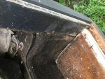
I paint all my stuff when I put it together just so it looks nice, but it has also been a good indicator of where things are rubbing or touching. I think it's hard to think of all the possibilities during a build, so I'm pretty cautious when I first get mobile and I try to keep a sharp eye out for anything I've missed.

from me: WILLYN--Thanks for chiming in...good info...

here's some pics with tape showing where I'm at right now, but I've decided to raise the box and I may move it forward(the cardboard template shows the top hole location of the steering box where I'll raise the box and 1" forward, but I may move it more), but it will depend on how low I want the tie rod so that I have clearance from the tie rod to pitman arm, but raising the box 2" from where it's at right now will help for sure. This will also raise the pan hard bar at the frame mount into the top hole or down one from the top, which will help with clearances and get things more to being 90* and no pan hard bar bend at the axle mount, I think.

img_5820-jpg.2817706

img_5821-jpg.2817714

img_5825-jpg.2817722

​​​​​​
img_5826-jpg.2817730
 
and some with measurements showing that my pan hard bar and draglink aren't running parallel....this is because the tie rod will hit the pitman unless I lower the tie rod, which defeats the purpose of high steer so I have to move the box forward. I know I can put a bend in the pan hard bar at the axle mount, but we only have 1 ¾" die for bending and bending it around the upper 3 link mount will result in the pan hard wobbling a bit and I think it could hit the upper link and that bend doesn't seem smart to me, so I'd like to use the smaller size DOM for the pan hard to help with clearance and keep it straight.
img_5822-jpg.2817746

img_5823-jpg.2817754
img_5824-jpg.2817762
 
steering is always fun. If I hadn't run across a decent deal on the Artec steering arms I may have looked really hard at double arms to put the tie rod behind the axle, as that would free up room for the pan hard bar if the tie rod could be put back there.

First thing on my agenda, now that I've given it some thought, is to drill out the Reid knuckle tie rod holes for a ¾" bolt and drill out the Artec arm, build the tie rod and mount it up to see if I need to use offset heims or regular heims. This will let me know how high I can mount the tie rod also to see what clearance issues I have with the pan hard bar and pitman arm of the steering box. This in turn will let me know how far forward I need to mount the box. I'm definitely going to mount it high on the frame rails though to get the pitman arm up as high as possible to keep it out of the rocks and to get the tie rod as high as possible. The bottom bolt hole centers will be about 1" up from the bottom of the frame, but I'll take a measurement tomorrow to make sure that's the correct dimension.

So with the weather supposed to be crappy I'm not sure how far I'll get this weekend, but these things always take longer than you think!!

So I removed the front tires and slapped on the calipers, the RUFF STUFF cover and drilled out the Reid knuckles and the ARTEC high steer arm for the ¾" bolt.
Slipped on some straight helms and cranked the tires all the way to hard right and hard left to see what would happen with the tape hitting the diff cover and looking at the pan hard mount. I decided to go with the offset helms and then took a measurement with the tires cranked hard right. I cut the 1 ¾" x ¼" wall DOM and slipped it onto the axle. Well dang it was too long. So then I took 2 pieces of 1"x1"x48" square tube and bungeed one to each tire and then measured at the front of the tire and at the rear side of the tire and got them set to the same measurement and then measured for the tie rod. I had to cut 1 ¼" off the first measurement. I guess there's no stop on the knuckle when you crank hard right or left. The stop is at the front of the opposing knuckle and that's why the measurements weren't the same. So good thing I had something available to bungee to the tires to get the wheels parallel. I'm at 88 ¾" outside to outside at the front. The tie rod is in the paint booth. Yea a lot of crap in the garage, because my brother still hasn't moved out all his stuff so it's cramped and hard to organize, so I have to make due and live with it.
img_5835-jpg.2819210

img_5837-jpg.2819226
 
Got the pan hard mounted and for those who want to know the frame mount is about 3 3/4" from center of mount to center of axle and the axle mount is 3 ½" from center of axle to center of the mount. It's made out of 1 ½" x ¼" wall DOM and is 36" long center to center right now. I'm not sure if I'll have to move it down a hole, which will make it 36 ½" long if needed.

Next up is the steering box and it's probably a 2-3 weeks away, since ol' bro says so. We are thinking the Durango box, as highly recommended by willys_mogon, and probably go with RedNeck Ram setup---https://westtexasoffroad.wixsite.com/wtor
I need to call them to see if they want an exact replacement or if we can send them one of the boxes that are sitting in the garage, since they have the option of ordering a new box and sending them a core later vs us having to chase down a durango junk yard box.

Question on pitman arms would you drill out a pitman arm to create a ¾" hole that has a diameter of 1 ½"? This leaves ⅜" thickness of material around the hole, is that too small for the bolt connection? Just wondering if he needs to buy a new pitman arm from WFO that you drill yourself.

Some full stuff pics---I'll probably cut down the panhard frame mount once I've got things dialed in and maybe the axle mount if we have to move it down a hole.
img_5845-jpg.2822242

img_5846-jpg.2822250

img_5847-jpg.2822258

img_5848-jpg.2822266
 
from TimCubed: I wish the panhard bar was longer on the axle side.......... I have opposed mounted panhard bars on my little one. Going 20+ MPH on a rolling fire road or the desert with lots of compression and extension, I can feel it rotate from center to left maybe 1 1/2" front and to the right in the rear. Anyway the longer the panhard bar the less rotational effect............. It looks like you can use the weld on threaded bungs on the same bar to extend the bar up to 2 1/2"? ...........OK, well that sounds like I just nitpicked your work, :flipoff2:

from me: Tim--I don't mind the nit-picking, cuz all input is good input--the panhard will match the draglink length and I have to factor in future anti-rock bar axle mount too. The pic is a little deceiving as it looks like there's more room to make it longer on the axle side, but there's not much further I could go, unless I did something like on the '48, which was build a mount off the front of the axle, which means moving the steering box even further from the axle and I never did really like the '48 panhard set up. I did look at putting it behind the axle too, but again that looked to be troublesome to clear the upper 3 link bar and I was still going to be the same length. We shall see what happens.

I got some measurements from Wildhorses on a 1979 Ford kingpin dana 60 and they said the panhard was 36", drag link 42" and tie rod 55". I didn't intend for the panhard to be the same but it is, and my draglink will be right around 36" and our tierod is longer, but right now I can't recall the exact length, but of course we have REID knuckles and they must be different than stock knuckles. Interesting that there's 6" of difference between the panhard and draglink, but we didn't get those with the axle, so I have nothing to compare it to.

Talking with RedNeckRam guys they stated this about Saggy boxes(saginaw):

1) that the Durango box must have for your ram assist steering box is a thing of the past. The Durango box was a must have when guys started putting bigger and bigger tires on because it could move these tires better than other boxes and then ram assist was added to mix, but now-a-days the tech upgrades to rams make it so they are better dialed into match the box that you have.

2) And also a small piston box is actually desired over the big piston box, since the big piston box and ram will have slower steering vs small piston box and ram. But I'm not sure you'd know the difference unless you installed one box and drove it for a couple of days and then switched to the other style box, but nevertheless there's a difference in the steering rate.

3) Bolt size or the amount of bolts for mounting your box are non-factors also, but you do of course want a sturdy mount.

4) Make life easy by matching your pump to your box for the hose connections. Pump mod is wise(this is on their site)

5) The casting numbers on the side of the box mean pretty much nothing, since GM put different internals in the same box and some have been around for many years.

6) If your box has a big Z cast on it this stands for Saginaw.

So hopefully I remembered all that correctly, but I think I did.

Steering box mount done...17" from center of axle to pitman shaft...raised it up too...night time pics aren't the greatest....also put the front crossmember in....

img_5868-jpg.2824114

img_5869-jpg.2824122

img_5871-jpg.2824130
 
Well I had to make a slight alteration and now after I've done it I may have to cut it out and redo it. Not that it's not right, but I'm not sure using a ½" bolt in the pitman arm for the drag link is big enough, so I'm thinking I may change it out to a ¾" bolt and also do I make the pitman arm double shear? The ¾" bolt head may clear but the double shear bracket probably won't. Oh well live and learn and learn I did that when you are putting the front crossmember you probably should get the steering box temped in and put the pitman arm bolt or tie rod end in the pitman arm and rotate it back and forth to make sure it won't interfere with the crossmember or frame.

Now more along that line with the ½" bolt being strong enough for the draglink connection at the pitman arm is it also strong enough for the connection at the steering arm? I'm not so again I may drill it out for a ¾" bolt and also double shear it with a mount off the steering arm. Anyone have any thoughts on this?

In the pic the bolt is a temp bolt until I figure out what I'm going to do.

Found my answer--¾" bolts is what will be needed. I pretty much thought this, but just wasn't sure, since tie rod ends are a tapered design.
img_5876-jpg.2825554

img_5877-jpg.2825562
 
Well I stretched the hood and fenders 3"(for radiator fitment) and made new hood hinge mounts with 5/16" coupling nuts as they were the perfect 7/8" height(I thought they were because they measured 7/8" and that's the height of the OEM hat channel mount), but for some reason I need to add in a 1/2" spacer(give or take) between the hood and hinge to get the hood to sit parallel to the fenders. I'm not quite sure why, but maybe it's because there were some 1/2" thick rubber bumpers on the cowl/hood lip that the hood closed against and maybe that held the hood up when closed, but they got knocked off with the new hood extended. Again not quite sure why this would happen, but it did to me.

I also reinforced the hood with some 3/4" "L" angle to attempt to keep the 3" extension in line with the hood--it worked to some degree, but not as perfect as I wanted. I had it clamped and stitch welded the extension on to try and minimize warping, but I still got some. I'll deal with it later as it's cosmetic and I've got plenty more more important things to do on this thing.

Pics later, but they're nothing that spectacular...

best I can do on the pics with the Pitbull's--cramped space--the rear is sitting about 5-6" above ride height..

and as promised pics of stretchiness....
54526529637__c649737f-5146-4c3e-a0b6-57036d01bb68-jpg.2857545

54526530703__d3787db4-119e-4530-a20f-b4686c70e1ce-jpg.2857553

54526738676__48e4c6e1-3848-4349-b1fe-543a6f59a112-jpg.2857561
img_5969-jpg.2857569

img_5970-jpg.2857577
 
I was asked what size the tires were: 39.5x16.5x17 on 17x9.5 rims

You may want to rethink attempting to sandblast your front grill with Harbor Freight's little portable sandblaster, unless you're a glutton for punishment like me!! It looks like it snowed two inches even though I have a cardboard backstop and 2'x4' tub. You can't control that stuff without building a full enclosure and then I'm not sure you could see what you're doing if you did, unless it was pretty good sized. I've got 22 hours into it and 200 lbs of glass bead purchased and am reusing what I can capture and filter and I'm around 95% done.(I have to buy more media to finish or I can just sand the rest off) I will say it does a real nice job, but it's slow and like Mieser said you do need to shake the tub to keep the media over the inlet. I didn't buy the Harbor Freight hardhat/hood because I figured a full face shield, glasses, ear plugs, dust mask and a hat would be fine, well it is and it isn't, because again that crap goes everywhere, so again if you want to jump on this band wagon I think the Harbor Freight hood would be smart. I did look into buying the larger blast cabinet, but I didn't think the grill would fit, but I sure kind of wish I would've taken measurements to know for sure, because again Mieser's suggestion that buying the cabinet may be smart, as it will contain the media so you don't have to buy as much, which in the long run will be smart. Back to blasting soon, oh the fun.....

The last time I was at HF to buy another box of glass bead I bought a couple of cheap plastic paint strippers that you chuck up into a drill and I spent another 2 hrs with one of them to complete the job. Next time I'll use that or have someone sand blast it for me, cuz it's messy and time consuming and more expensive than I thought it would be to sand blast with that little portable sand blaster. It's great for small things, but it's still messy.
 
Radiator, shroud I built and taurus fan installed in a clamping angle iron mount welded to the front cross member and the oil cooler mounted to grill with 5/16" all thread....the radiator sits on some rubber pad in two "u" shaped brackets and I used shower pan liner between the brackets and radiator. Got some quick disconnects coming for the oil cooler to easily remove the grill if needed.
img_6033-jpg.2871066

img_6034-jpg.2871074

img_6035-jpg.2871082

img_6041-jpg.2871090
 
from Alcurtice: Nice radiator mount - definitely heavy duty. It looks like you cut out the original radiator mount from the grill. That should free up about 2" of room there I would think. I should have done that too, I could have used the extra space.

from me: Yea I cut that out or I would've had to stretch the front even more and I didn't want to go more than 3" on the stretch. To get the radiator to fit there with a 3" stretch I had to notch the passenger side headlight bucket also. With a wider radiator I'd've had to stretch more again. I will also probably add some sort of mount to the top of the radiator once I do the shock tower bracing over the top of the motor to make sure the radiator can't move up and down, since it's only clamped and there's no mounting bolts.

Grill installed— I’m not sure I’ll keep the blinker lenses, will make a decision once I can see them lighted up--there's LED lights behind them and the headlights are LED also. At first I thought for sure the lenses should be removed, but now I'm not sure. Next up is the front anti-sway bar, which will require cutting out some of the front fender to allow for arm clearance as it rotates up. But with that being said I've been mulling over tube fenders for sometime now, so it may be the prudent thing to do for protection, although the fenders may never contact much since the tires stick out and doing tube fenders may help with integration of the sliders. Front of truck is at full stuff right now and the anti-sway bar will be going thru the frame vs under it, but it will be a little below center of the frame, as I want the bottom of the arms to flush with the frame for some added protection.
0736ca4f-e4ea-4e58-8603-5d8d0c1a3cd1_1526396121599-jpg.2873833
 
Top Back Refresh