What's new

1990 Cherokee XJ Build

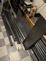
I built my own links. Use PVC to measure everything. It’s cheaper than metal and works well.
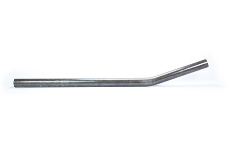
Remember when you're welding in the bungs to use anti seize, and let it cool. I welded mine with the joints in the bungs. I drilled holes to plug weld the bungs, then welded them about 1/4 at a time making sure to move and take my time to not get it too hot.
I would also say to remember to have the joint/heim fully threaded into the bung with the locknut before making final measurements. It really does surprise you how little adjustability you can have with a 1 1/4” joint.
You’ll get to decide if you want LH/RH or both LH (or RH) threaded joints. I went with LH/RH.

It’s just welding and measuring. I didn’t know how to weld or read a tape measure when I started. Now I’m on electrical headaches.
 
The PVC is a great idea actually, thanks! I appreciate the tips.

Yeah when I see the prices of these suspension links/tie rods/track bars/etc. now that I know how to weld, what DOM costs, and what the joints cost, I can’t justify paying that price for them, when I know I can do it myself no problem. However, I’ve never done it yet, so, I appreciate the advice.

The only “hard part” is that the IRO kit uses bent links, I assume because of where the crossmember has the links coming out of it…

IMG_5311.png

The IronMan kit, has the links coming from the center, rather than the outside. I can’t tell yet if those bends are going to be mandatory or not, to clear the tires, but, I don’t think they are?

If I need the bends, I definitely don’t have a bender that can bend DOM that thick, without kinking the shit out of it.

Oh, what size are you actually using for end links/joints? Are you doing the bushing type, or heims? I was thinking about either using some sort of rebuilding bushings (ballistic fab makes some cool looking ones) or using ones like these: https://a.co/d/7OOvA7D (not necessarily that listing, or size, but, that type)
 
Last edited:
IMG_5361.jpeg


Got everything loosely hooked up just to make sure it fits. Definitely a steeper driveshaft angle but I knew that would be the case. (Blue line is my approximation of the previous High Pinion setup)

Also, I accidentally bought adjustable cam LCA mounts, but, in this pic the cam adjuster plate things haven’t been welded on yet, and I also got cam delete washers that I will probably just weld on as well, so, that won’t be an issue.

I did a Johnny Joint in the UCA mount, with a 5/8” bore, so had to ream my UCA linkage end to 5/8” real quick, and I used one of those Zerk’d bolts for that.

IMG_5354.jpeg


I got drunk and bought $200 worth of >1/2”-13 Grade 8 nuts and bolts, because that was the largest size bolt that I had a lot of.

IMG_5350.jpeg


Once I verified that everything seemed to fit as intended (except for the track bar, that mount needed to be rotated outward a bit from where I originally tacked it) I started welding everything.


IMG_5366.jpeg


I then got 80% of the way done and of course ran out of both CO2 and weld mix, and no one fills that shit within 100 miles of me on weekends apparently… so I’ll have to finish it up this week so I can paint it.

Trying to have this wrapped up by this coming weekend for the Cal4x4 thing at Hollister Hills, but if I can’t, I’ll have to just throw the old axle in there ugh.

I’m also nervous about this driveshaft angle. It’s not binding but it is much steeper than previously, and I don’t have any springs that are less than 7.5” on hand.
 
I used the biggest MetalCloak joint they maid. It runs 9/16 hardware and I’ve learned it is an uncommon size.

Definitely turn your welder up a heat setting. Your weld is standing tall. It’s cold. You need to turn the heat up a tad so it really packs in there and penetrates. Especially on the track bar.

Don’t let a meet up at Hollister Hills make you rush anything. Do it right so you don’t have to do it twice.
 
IMG_5361.jpeg


Got everything loosely hooked up just to make sure it fits. Definitely a steeper driveshaft angle but I knew that would be the case. (Blue line is my approximation of the previous High Pinion setup)

Also, I accidentally bought adjustable cam LCA mounts, but, in this pic the cam adjuster plate things haven’t been welded on yet, and I also got cam delete washers that I will probably just weld on as well, so, that won’t be an issue.

I did a Johnny Joint in the UCA mount, with a 5/8” bore, so had to ream my UCA linkage end to 5/8” real quick, and I used one of those Zerk’d bolts for that.

IMG_5354.jpeg


I got drunk and bought $200 worth of >1/2”-13 Grade 8 nuts and bolts, because that was the largest size bolt that I had a lot of.

IMG_5350.jpeg


Once I verified that everything seemed to fit as intended (except for the track bar, that mount needed to be rotated outward a bit from where I originally tacked it) I started welding everything.


IMG_5366.jpeg


I then got 80% of the way done and of course ran out of both CO2 and weld mix, and no one fills that shit within 100 miles of me on weekends apparently… so I’ll have to finish it up this week so I can paint it.

Trying to have this wrapped up by this coming weekend for the Cal4x4 thing at Hollister Hills, but if I can’t, I’ll have to just throw the old axle in there ugh.

I’m also nervous about this driveshaft angle. It’s not binding but it is much steeper than previously, and I don’t have any springs that are less than 7.5” on hand.

3 concerns:

1. That driveshaft angle isn't correct for a double-cardan. With a double cardan, the u-joint at the pinion should have as close to zero angle as possible. You'll have to rotate the axle forward, which will lose caster (see my concerns previously :flipoff2:). Not sure if there's pinion angle change through travel (I assume this is full bump, set pinion angle at ride height), so maybe it's not as bad, but if it's anything like that, it's bad.
2. That slip-yoke is waaaaaaaaay extended. Is there any spline engagement there? If so, it can't be much...
3. See below


Turn the machine on the highest setting and run a cap pass on that.
Yeah, too cold. Crank it up, it's 0.25" wall, most home welders aren't going to blow through unless you get stupid with it. :flipoff2:
 
Turn the machine on the highest setting and run a cap pass on that.

I used the biggest MetalCloak joint they maid. It runs 9/16 hardware and I’ve learned it is an uncommon size.

Definitely turn your welder up a heat setting. Your weld is standing tall. It’s cold. You need to turn the heat up a tad so it really packs in there and penetrates. Especially on the track bar.

Don’t let a meet up at Hollister Hills make you rush anything. Do it right so you don’t have to do it twice.
Thanks guys, will do.

My welder is 110/220v, and I put in a 220v drop out in the garage. So, the "highest setting" is 160 amps, should I really just crank it up all the way?
 
3 concerns:

1. That driveshaft angle isn't correct for a double-cardan. With a double cardan, the u-joint at the pinion should have as close to zero angle as possible. You'll have to rotate the axle forward, which will lose caster (see my concerns previously :flipoff2:). Not sure if there's pinion angle change through travel (I assume this is full bump, set pinion angle at ride height), so maybe it's not as bad, but if it's anything like that, it's bad.
2. That slip-yoke is waaaaaaaaay extended. Is there any spline engagement there? If so, it can't be much...
3. See below


Yeah, too cold. Crank it up, it's 0.25" wall, most home welders aren't going to blow through unless you get stupid with it. :flipoff2:

1. It is in the rear... but, I thought they just needed to be parallel angles, like so:
1715021794049.png


? That's what I was going for when I mounted all the bracketry at least... (Though obviously I can't do much about the C's, other than cut and turn, which I'm trying to avoid.)

2. I was worried a bit about that as well, there is as much engaged as the blue neoprene in the photo. (5" of blue neoprene, it's a full 7" slip stub [Adam's Driveshaft], and it is 50% engaged, so, there are 2.5" of slip stub in that yoke. Adam's recommends 2" max, so I'm pushing it a little. But, was going to see if I could even get the angles to work and how bad vibration was, before I figured out how to deal with the driveshaft length issue.)

Guess I need to lower her... :(
 
Thanks guys, will do.

My welder is 110/220v, and I put in a 220v drop out in the garage. So, the "highest setting" is 160 amps, should I really just crank it up all the way?
Get some scrap 3/16 metal. Cut some 8" long sections and make T joints. Leave the wire speed where you have it and turn the heat up a mark then weld an inch. Compare it to your weld, then turn the heat up again and see how the weld changes. Too much will have the mig wire creating lava drops kind of shaped like a rain drop. Back off the heat at this point.

What machine is it? I know Lincolns are A/B/C/D/E and others are a dial where you can adjust it to any voltage.
It's a cheap chinese welder off of Amazon lmao. :D

I didn't know that I was going to be doing so much welding when I decided "I should probably learn how to weld..." and so didn't invest a ton into it.


I may upgrade to a 200A now that I am welding much more often (and now that I have CO2 and Argon tanks, which I didn't have when I bought this [was just using flux core for the first few months]). I obviously don't have anything to compare it to, but, I think it actually works pretty damn well for the price. Especially when you consider that Miller's are 5x the price (new, anyway). These "YesWelder" and "ArcCaptain" welders though are essentially Miller-matic clones, and have pretty decent reviews on YouTube from guys that have been welding for years...

I can adjust voltage/amperage/wire feed speed on this one though, so, can dial things in pretty precisely. I just am not an experienced enough welder to really know exactly what looks good and what doesn't. I've watched a hundred YouTube videos and the guys will be like "This weld looks like shit! Now watch this one, this one is perfect!" And they basically look the fuckin same to me...

Thank you guys for all your help though, for real!
 
What voltage do you have it set at, and what Feet per Minute is it at? Looks like your machine doesn’t give you inches but math isn’t hard.

I THINK I was doing 17.4-17.7 volts and 160 INCHES per minute when I started and was comfortable, relaxed and calm.

My welder is a Viper MiG. It’s from Australia or something. It’s a 180 amp. A 140 amp would probably be sufficient for what we do. Indian not the arrow.


Basically, when you make a T joint you want the weld to look like a 45 degree angle. 📐
If the weld looks like a worm crawling in the crack it is too cold. You weld looks like a worm. It’s too cold.


Post in the ‘Your Shitty Weldz’ thread and ask for help. PLENTY of guys here are self taught. I was a rich kid and spent some COVID bucks on a welding class at the community college. Greatest thing ever.
I have friends who took welding in High School, I did woods instead...

I will check when I get home what I had it set at, but I use the auto setting for the most part when I am doing gas mig. When I was doing flux core, if I didn't turn down the WFS manually, I'd end up blowing through shit (especially thin stuff like the XJ unibody rails). For those welds, I had it set at ~100 amps if I remember correctly, and then it does the voltage automatically. I can then adjust the voltage +/- from the auto setting, but I just left it where it was.

I will definitely use that thread. As I was standing back looking at the axle mess I created, I was thinking, "Fuck, this is when I really have to trust my welds..." because up until now, I had just been building shop tables, welding on frame stiffeners, making light bar brackets, etc. But now I'm at the "if this fails at speed, this is going to cause an accident..." step...
 
you can always buy material to practice with. Maybe find a free bed frame on craigslist and build a welding cart or random stuff out of it. I’ve lost a lot of skill I had just because I wasn’t welding 8 hours a week.
 
you can always buy material to practice with. Maybe find a free bed frame on craigslist and build a welding cart or random stuff out of it. I’ve lost a lot of skill I had just because I wasn’t welding 8 hours a week.
Bed frames are shit steel. They sweep the floor and melt it down to make bed frames. If you have a local steel place, see if they will let you rummage through their scrap bin. Mine usually has some good shit and it’s by the pound cheap…
 
Bed frames are shit steel. They sweep the floor and melt it down to make bed frames. If you have a local steel place, see if they will let you rummage through their scrap bin. Mine usually has some good shit and it’s by the pound cheap…
It’s good enough for my welding cart, and practice.
 
Bed frames are shit steel. They sweep the floor and melt it down to make bed frames. If you have a local steel place, see if they will let you rummage through their scrap bin. Mine usually has some good shit and it’s by the pound cheap…
Yeah there’s an Industrial Metal Supply like an hour north, they sell remnants for $0.70 a pound. Love this place, they have everything, but I’ve never needed something and not been able to find it in the remnants.

I went nuts and bought a bunch of stuff just to have on hand, because of course they are only open M-F, 8-5PM, which is when the rest of us work… so, it’s not easy to just run by and grab stuff.


IMG_2199.jpeg IMG_2545.jpeg IMG_4798.jpeg

The table was the first thing I ever welded, and all flux core, so it’s a chewed gum mess. Sturdy as fuck though and weighs about 300lbs.
 

Attachments

  • IMG_2393.jpeg
    IMG_2393.jpeg
    2.8 MB · Views: 7
  • IMG_2385.jpeg
    IMG_2385.jpeg
    2.4 MB · Views: 7
  • IMG_2340.jpeg
    IMG_2340.jpeg
    2 MB · Views: 5
  • IMG_2261.jpeg
    IMG_2261.jpeg
    2.8 MB · Views: 8
  • IMG_2232.jpeg
    IMG_2232.jpeg
    2 MB · Views: 5
  • IMG_4795.jpeg
    IMG_4795.jpeg
    1.5 MB · Views: 7
For links you’ll want 1 3/4” or 2” DOM and 0.25 wall thickness.

$0.70/pound sounds like a good place to spend beer money to me. The more time you spend welding the better, hopefully, you get.
 
1. It is in the rear... but, I thought they just needed to be parallel angles, like so:
1715021794049.png


? That's what I was going for when I mounted all the bracketry at least... (Though obviously I can't do much about the C's, other than cut and turn, which I'm trying to avoid.)

2. I was worried a bit about that as well, there is as much engaged as the blue neoprene in the photo. (5" of blue neoprene, it's a full 7" slip stub [Adam's Driveshaft], and it is 50% engaged, so, there are 2.5" of slip stub in that yoke. Adam's recommends 2" max, so I'm pushing it a little. But, was going to see if I could even get the angles to work and how bad vibration was, before I figured out how to deal with the driveshaft length issue.)

Guess I need to lower her... :(
1. You're right. Sorta. I saw links and ASSumed it was the front and double cardan. If it's a standard single U-joint on either end as depicted above, then it needs to be parallel on either side to cancel. If it's double cardan however:

1715093088687.png


It needs to be straight out of the yoke, as the double cardan joint is self canceling. I assume you're running an SYE with a double cardan driveshaft?

2. I wouldn't worry too much: that's at full droop and you're not going to have any traction there to stress the splines.

Lower is better, but not necessary, just need to consider everything that'll fuck you. :flipoff2:
 
Last edited:
the image with the driveshaft is in the front. If that’s at ride height, you’re going to need to turn the Cs. I am running 8 deg castor on lp30 with 3.5 inch lift and I need to turn the Cs.
You could also push the axle toward a few inches to help a little bit with the angle but it will only help a little and create more issues you need to deal with
You can dick around with ZJ front driveshafts, cheap, if you want a longer shaft

Is that the SFR 3/4 link? looks like it. That kit uses shorter upper arms to keep good castor through suspension travel. Good for jeep speed type of deal, but will point the pinion downward as well through the suspension travel so your angle will get worse through droop
 
It's a cheap chinese welder off of Amazon lmao. :D

I didn't know that I was going to be doing so much welding when I decided "I should probably learn how to weld..." and so didn't invest a ton into it.


I may upgrade to a 200A now that I am welding much more often (and now that I have CO2 and Argon tanks, which I didn't have when I bought this [was just using flux core for the first few months]). I obviously don't have anything to compare it to, but, I think it actually works pretty damn well for the price. Especially when you consider that Miller's are 5x the price (new, anyway). These "YesWelder" and "ArcCaptain" welders though are essentially Miller-matic clones, and have pretty decent reviews on YouTube from guys that have been welding for years...

I can adjust voltage/amperage/wire feed speed on this one though, so, can dial things in pretty precisely. I just am not an experienced enough welder to really know exactly what looks good and what doesn't. I've watched a hundred YouTube videos and the guys will be like "This weld looks like shit! Now watch this one, this one is perfect!" And they basically look the fuckin same to me...

Thank you guys for all your help though, for real!
Your travel speed looked reasonable (hard to tell since it was wire-wheeled, but this assumes the HAZ isn't gigantic). Adjust the welder, increasing wire feed and voltage, until that travel speed results in a weld large enough to fill the entire joint without blowing through or melting the corners off of shit. As long as you're getting that good sizzling zzzzzzzzzzzz sound, you're balanced correctly between V and wire. My assumption is with a "160A" welder, you're going to be nearly maxed out on both V and feed to get it to wet in correctly.


This dude's videos are great. He's the Bob Ross of welding to me. Notice that he's moving fast enough that the HAZ is somewhere around the same size to double-ish the weld itself on either side, that outside corner joint has a nice sharp edge, and the welds themselves are shiny and not grey? If you're making a huge balloon of HAZ and the weld looks grey after it cools, you're moving too slowly.

160A is enough for 1/4" as long as you're patient with temps on the welder itself. Since most of us aren't doing FRP assembly line welding, just the time it takes for you to fabricobble a new chunk of steel to glue on is plenty of time to cool off the welder.

Also: A and wire feed are related. Volts is the "heat". :flipoff2:
 
1. You're right. Sorta. I saw links and ASSumed it was the front and double cardan. If it's a standard single U-joint on either end as depicted above, then it needs to be parallel on either side to cancel. If it's double cardan however:

1715093088687.png


It needs to be straight out of the yoke, as the double cardan joint is self canceling. I assume you're running an SYE with a double cardan driveshaft?

2. I wouldn't worry too much: that's at full droop and you're not going to have any traction there to stress the splines.

Lower is better, but not necessary, just need to consider everything that'll fuck you. :flipoff2:
Correct, double cardan.

I don’t know why I assumed that they needed to be just parallel/equal angles, now that I’m looking at all the pics I took before I took it apart, I guess it was pretty damn angled…

IMG_4851.jpeg


Well, I am open to the idea of cutting and turning the C’s if I must…

What do you guys think, bandsaw? The tubes are sleeved, and the sleeves are welded at the ends, in the C’s. I will have to grind out those welds before I can cut the axle tube itself, and then rotate the axle tube on the sleeve tube, then re-weld, I would think? I like the idea of keeping the sleeve intact, because then it’s at least got that for strength.

EDIT: Well, there are two ways to do this… cut/grind out the welds on the C’s themselves, turn the C’s, and weld back onto the tube. This will work but this does not help the fact that my spring perches may cause some bowing… (although I did weld them on tilted downward [toward the rear of the Jeep] about 2.5* to mitigate this.

Second way would be to grind out the plug welds at the housing, and rotate the housing itself. Here’s the thing though, I already HAVE that HP D30, that is already geared to 4.56, so, if I did this, I could just swap housings, and create a HP WJ Frankendana 30…. Only problem here is that the videos that I have seen of people grinding out the plug welds and pressing the tubes out of the housing looks like a HUGE pain, and I just have a little 12 ton HF press, it’s not even big enough to get it on there. My thought a few weeks ago was just to swap the axle tubes between the two housings, (cut the tubes maybe an inch from the housing) but leave the sleeves intact to act as a truing bar essentially. Then hammer the axle tubes on over the sleeves. This way I can rotate C’s however I want, and I also would have the HP D30 housing. (Remember, my goal is to use the WJ axle tubes and RCV axles I have, keep the 5x5 bolt pattern on the WJ, as well as retaining WJ knuckles for the big brakes and OTK steering setup I have as well.)


How fucked am I, and what’s the best way to do this? I don’t mind the time/effort, I just am wondering what the ideal way to do this would be, to do it right. (inb4 “buy a D44,” I probably will one day, but in the meantime I’ve got all these parts already, and time on my hands, and I enjoy learning and doing the work.) Both axles are already removed from the Jeep, and I have a welder and a fuck ton of tools, so, I’m in a good spot to do it “right.”
 
Last edited:
the image with the driveshaft is in the front. If that’s at ride height, you’re going to need to turn the Cs. I am running 8 deg castor on lp30 with 3.5 inch lift and I need to turn the Cs.
You could also push the axle toward a few inches to help a little bit with the angle but it will only help a little and create more issues you need to deal with
You can dick around with ZJ front driveshafts, cheap, if you want a longer shaft

Is that the SFR 3/4 link? looks like it. That kit uses shorter upper arms to keep good castor through suspension travel. Good for jeep speed type of deal, but will point the pinion downward as well through the suspension travel so your angle will get worse through droop
Yes, SFR 3 link.

Damn, thank you for this info. I will absolutely have to turn C’s then if you had to, on a 3.5” lift.
 
After al that you can put a pair of axles from a 2005+ super duty under it. :flipoff2:


Edit: I second the comment about Bob Ross of Welding. I watched a lot of his videos when I was taking a class and it’s all true. Weld Tube has some good videos of the puddle and what you’re looking to do. Again, post in any of the welding threads anywhere here.
 
Last edited:
Hey guys… I figured out why the WJ spring mount brackets are 2” taller than the XJ brackets…

IMG_5452.jpeg
IMG_5454.jpeg

This was the first time I had put the tie rod on and actually turned the wheels from side to side…

Moooother fucker. It hits the spring mounts with probably 20% more to go before the steering stops hit…. And yes, it has offset heims already.

Welp, now I’m looking at Clayton Offroad’s HD WJ spring mount buckets… maybe I can salvage these and cut them off clean enough that I can use them on my HP D30…
 
Yes, SFR 3 link.

Damn, thank you for this info. I will absolutely have to turn C’s then if you had to, on a 3.5” lift.

I would drive it first, you might be able to tolerate the vibrations, except the angle will put more stress on the u joint.
I have not actually cut and turned my Cs yet I dont really want to put any time or money into the LP, i barely convinced myself to do the balljoinnts on it,
it doesnt vibrate that bad but the angles are defiantly wack, ill try to post a picture. But once you drive with 8+ degrees of castor, it makes some slight vibration worth it.

edit since you posted while typing:
maybe you can put a bend in the tie rod, see if you can fix what youve got before hitting the parts cannon
Do you know if you can do a bend AND use the offset tie rod ends?

I’ve seen plenty of the “high clearance” bent tie rods, but never have seen one that also uses offset ends. I mean I wouldn’t think it would matter, but I’m not sure. Just seems like it will end up being awfully “offset” lol.

Thanks for the tip man.

Edit: I know cavfab makes an offset tie rod specifically for WJ knuckle swaps:

I don’t think I can bend this tie rod without kinking it…

Edit 2: The link above of course won’t actually fit on a true WJ D30. IRO makes one that will: WJ Over the Knuckle Tie Rod Kit

I would need to get measurements from them, I think their bend is still too far from the tie rod ends to clear the spring mounts…
 
Last edited:
Correct, double cardan.

I don’t know why I assumed that they needed to be just parallel/equal angles, now that I’m looking at all the pics I took before I took it apart, I guess it was pretty damn angled…

IMG_4851.jpeg


Well, I am open to the idea of cutting and turning the C’s if I must…

What do you guys think, bandsaw? The tubes are sleeved, and the sleeves are welded at the ends, in the C’s. I will have to grind out those welds before I can cut the axle tube itself, and then rotate the axle tube on the sleeve tube, then re-weld, I would think? I like the idea of keeping the sleeve intact, because then it’s at least got that for strength.

EDIT: Well, there are two ways to do this… cut/grind out the welds on the C’s themselves, turn the C’s, and weld back onto the tube. This will work but this does not help the fact that my spring perches may cause some bowing… (although I did weld them on tilted downward [toward the rear of the Jeep] about 2.5* to mitigate this.

Second way would be to grind out the plug welds at the housing, and rotate the housing itself. Here’s the thing though, I already HAVE that HP D30, that is already geared to 4.56, so, if I did this, I could just swap housings, and create a HP WJ Frankendana 30…. Only problem here is that the videos that I have seen of people grinding out the plug welds and pressing the tubes out of the housing looks like a HUGE pain, and I just have a little 12 ton HF press, it’s not even big enough to get it on there. My thought a few weeks ago was just to swap the axle tubes between the two housings, (cut the tubes maybe an inch from the housing) but leave the sleeves intact to act as a truing bar essentially. Then hammer the axle tubes on over the sleeves. This way I can rotate C’s however I want, and I also would have the HP D30 housing. (Remember, my goal is to use the WJ axle tubes and RCV axles I have, keep the 5x5 bolt pattern on the WJ, as well as retaining WJ knuckles for the big brakes and OTK steering setup I have as well.)


How fucked am I, and what’s the best way to do this? I don’t mind the time/effort, I just am wondering what the ideal way to do this would be, to do it right. (inb4 “buy a D44,” I probably will one day, but in the meantime I’ve got all these parts already, and time on my hands, and I enjoy learning and doing the work.) Both axles are already removed from the Jeep, and I have a welder and a fuck ton of tools, so, I’m in a good spot to do it “right.”

Run it and see. I wouldn't put THAT much work into a turdy, and I'm a sorta kinda fan of them. It'll be a tradeoff between vague/scary steering and driveline vibrations. Either way, cruising 80 on the freeway isn't happening. :flipoff2:

Hey guys… I figured out why the WJ spring mount brackets are 2” taller than the XJ brackets…

IMG_5452.jpeg
IMG_5454.jpeg

This was the first time I had put the tie rod on and actually turned the wheels from side to side…

Moooother fucker. It hits the spring mounts with probably 20% more to go before the steering stops hit…. And yes, it has offset heims already.

Welp, now I’m looking at Clayton Offroad’s HD WJ spring mount buckets… maybe I can salvage these and cut them off clean enough that I can use them on my HP D30…
Is it the tabs/sway bar mounts that are hitting, or the spring perch itself?
 
Hey guys… I figured out why the WJ spring mount brackets are 2” taller than the XJ brackets…

IMG_5452.jpeg
IMG_5454.jpeg

This was the first time I had put the tie rod on and actually turned the wheels from side to side…

Moooother fucker. It hits the spring mounts with probably 20% more to go before the steering stops hit…. And yes, it has offset heims already.

Welp, now I’m looking at Clayton Offroad’s HD WJ spring mount buckets… maybe I can salvage these and cut them off clean enough that I can use them on my HP D30…

Either make a new tie rod with bends and normal joints, or cut a notch out of the sway bar mount to clear everything, and add some 3/16 plate or a half round of tube in there for clearance. Similar to guys notching the frame for steering at full bump.
 
Top Back Refresh