What's new

1972 F-250 2wd to 4wd build

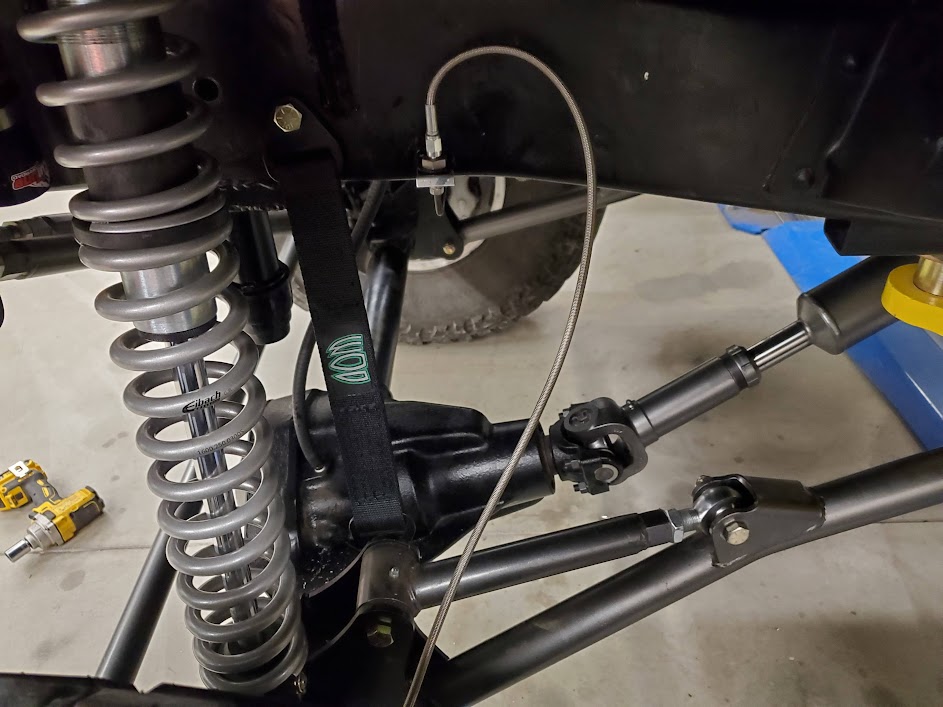
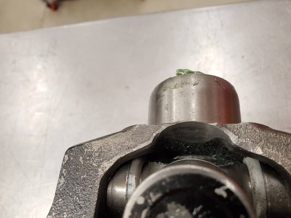
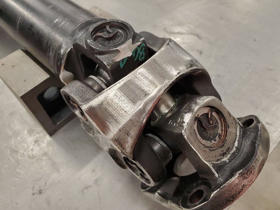
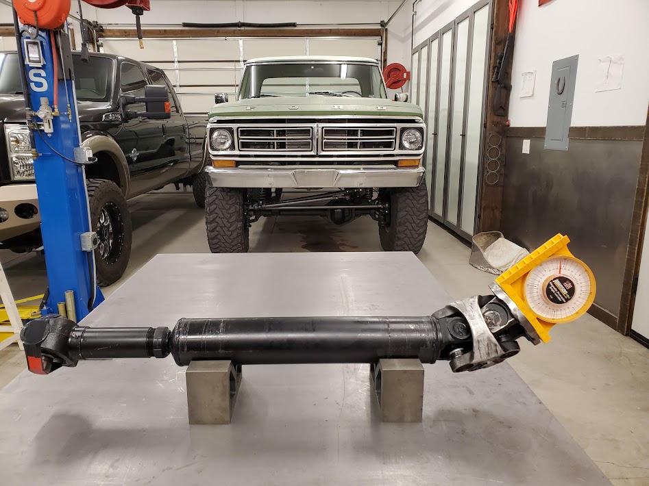
1350s are good for 20deg of angle stock and 1410s are good for 35deg, can get more with grinding of course. im not great at math but that extra 15deg should get you the extra 5" of drop as your front shaft should be fairly long. just something to think about as its easy to build a drive shaft but turning Cs sucks balls. i removed 1 of mine and thats a job i would not want to do again and i wasnt trying to save the C on my axle or axle tube off the donner axle
 
Thanks again for the help. I guess I need to run the numbers again and see if a 1410 setup is a option. I had gone down this path already but don't remember the specifics.
 
Did some more research on the driveline debacle.

I created an angle calculator in Excel to be able to try all types of combinations through the range of suspension travel. It compensates for pinion angle change and axle position as it moves through the arc. Also put in capacity for ball joint shims and caster adjustments. With all this the angle of the shaft and hence the u-joints can be calculated. It does not handle the extra angle due to diff being offset from transfer case horizontally. Only the TC end is a problem, whether or not I cut-n-turn the Cs. Cut and turn gets me only 5* more @ TC joint.

I called Tom Woods for info on going 1410. I was told (and found elsewhere) a 1410 double cardan will also only go to 30*, so little or no benefit to that path. Poo.

A 1410 single joint can go up to 37, but is dependent on the exact setup. A single cardan shaft will vibrate much more as geometry would be totally out of whack. A 1350 single is good for about 20, so a big gain in a single 1410 setup. Would have to buy a yolk to replace drive flange on TC, and a 1410 yolk on pinion end (or 1350 to 1410 conversion joint).

I measured the 1350 setup I have. It binds at 31 in one plane and 27.5 in the other. Installed in truck I measured bind at 26 including horizontal angle. I found contact of joint caps to the inner bridge so plan to investigate potential improvements. If I can get 30-31 out of the 1350 I think I can make it work. 2* ball joint shims, 4* caster. Would bind at current limit strap limits.
 
Pulled the double cardan joint apart and measured the angles of where the u-joints contact the various parts. Started with the inner bridge and drive flange that are the most inner contacts.
ACtC-3cjyNM_3Wicj4VX3pK9vDu4NPr-98psjGkA3JccyswAX4x-1EYCBPo87T3YUQZF9POJjUKjYM6Y9T2meaiXkHBtBZw9e5TJyboiIsZMxFG-6Edg_mHrbTmdh0a5R3vxqyDVo5gupT1cpkbYIwsXTgmc=w947-h710-no


The main offender was the area where the grease zerk is, it allowed only 14*, the opposite side was 18*. So I ground it out carefully to leave the dust boot intact. Now both have 18*.
ACtC-3dWUZiRyWC9efLBdFeLq6AJ2Dda7JQvG-RgRgxVB3czKZZJggYEpGXKOU3YOtUaZeHsYe_5XZysadKhgM7bhBJCsFNGcIUuBj9wOII00OuDYkPw8WRL1TU9zjWScXe8iZgYm_s8RP9t3aCqFpEJE_G1=w947-h710-no


Next was the flange side, they were about 16* so took them to 18*. Had to hog it out past the seal lip.
ACtC-3djTEXks4_VgtY0ulLY50ajg_PY_QAeLPDPkJ2Om3KQi-vq0_qbhT6aEbz9e0CIX2TpIDKSiboU8zjzXW6-SFsTglGHN7u6GDQ7xkjWsKsKNJeUD0uYhr0hdMi70OENApqA4_A1MVQlLZpMYkavjPf3=w947-h710-no

ACtC-3exiTsnmBw_3dQ7-iwdh7X8bGmRiRCtqdcL58yVJvZ4yigqoD-EM09aP_Wily8mM_hWA0jOse3NOppCNy3Kpy4GGoLvUJBF2IrEuHfYCBVqSf_tkCFoEmZ493IuYLqYhyrQdaneQ0lNbLDclzFO9-eZ=w947-h710-no


At this point I reassembled the joint and checked for interference. The new bind point was on all the external surface so I went around and ground them until they were no longer the limiting factor.
ACtC-3dpFAJerXomCu5eNlW56VvswBZCGddD--wh-Z9aKjuBkl2TYbz67DZLsJjy7RHXz-4br5LRAOGFHKetSElgjmFT68IbwuzOYuUpMt1iuMMfCHZCmQo1QtiC0UFTRQTMUuAamV3Gfjlm36psSgz-gPLt=w947-h710-no


Then measurements to see what I got. In theory 18* on each cross should get 36 total. It yielded 32 on one plane and 34 in the other. The contact point was the inner drive flange so I removed and hogged it out some more, to 20*. Reassembled and now its at 34 all around. So a major improvement from 27 to 34 (~25%). Compound angle is 38*
This should be enough to do what I want. Next step it to install the shaft in the truck, put it up on the lift and see where limits are. Way easier than turning the C's
ACtC-3eV3ymGBl_7fdXW4RW6y2vLO4JEvLwLs21NLk-Wxha3U2yAWTYicbaA8586wh0zUS9H867z1Hx5sbpnNgW1ABMi7OFOyZxMrrXo5wgBWAiM3di6_SrnIDgfbI2HC5TQIZQv7mIazjfMtL90nAAZZJhL=w947-h710-no
 
Last edited:
Nice to see the driveshaft tech. I am guessing you are planning to live with what you can get since you are still 4º shy of what you need?
 
Nice to see the driveshaft tech. I am guessing you are planning to live with what you can get since you are still 4º shy of what you need?

I figured I post some pics as I didn't find much at all on the web, interestingly. Maybe there are some long winded youtube videos with no results. Anyhow, I got more than I needed so its all good. 30-31 was minimum with other shenanigans, I got 34 so have some margin left.

Installed the driveshaft with truck on lift at full droop, there was another inch or so the axle could droop beyond the limit straps. This is with caster at 6*, so no other changes needed.
Driveshaft is at 24*, front UJ at 14*, TC UJ at 32 (vertical only)
B8J_Opf64Rk6UMd3nBN2fwi46P=w947-h710-no?authuser=0.jpg


At ride the U-joint angles are 15 and 25. I ordered some 2* ball joint shims to tilt pinion up. Not needed but easy and cheap enough to ease front joint operating angle. Should get me to 13/24 or so. Filled front diff with gear oil and went for test drive. Didn't notice any vibrations at low speeds. Steering with Spartan up front is not too bad in 2wd/hubs locked. So it's finally a 4WD.

Plan to revisit the limit straps. I needed to get them on to protect the drag link as well when using 2 post lift, so had to guess on length. I used an existing hole in frame that is a compromise so next step is install BJ shims and figure out new max droop point of driveshaft. Then adjust strap mount point or even get a different length. Should be able to get another inch down travel for 5 up and 6.5-7 down.
 
man that seams like it was a lot less work then rotating the Cs :beer:
 
Hell ya I'm pretty stoked about not having to do that job. Thanks again for helping me pursue other options.

Had to up to 65 mph with hubs locked and no noticeable vibes from front shaft. Didn't expect that but Ill take it.

So now with working front axle I drove up a dirt pile to find next interference issue. Rear tire gets into front of wheel well, then back also and contacts the inner well too So I think I have to be happy with it and extend bump stops to prevent sheet metal damage. The bump stop extensions are already long so considering other options like integrating with spring plate or some type of goofy custom block.

Can see tire bending fender into toolbox.
ACtC-3cgQrJTXAljjFFaS4vfsWm4b6H5e2utwSqn-CUPKhAktCodkMkkbHSoLKoLSYilxUG3mCxM911eecDVY-BkIugzhCBoYqs20dhbbODjjZBKpeydGCeu7h3LXqvEV4IFCVn9GiuK4NXPjuxoFWxz4zSj=w944-h708-no
 
Last edited:
Hell ya I'm pretty stoked about not having to do that job. Thanks again for helping me pursue other options.

thats what forums and build threads are all about :beer: im just happy it worked out for you
 
Hell ya I'm pretty stoked about not having to do that job. Thanks again for helping me pursue other options.

Had to up to 65 mph with hubs locked and no noticeable vibes from front shaft. Didn't expect that but Ill take it.

]

Damg... I have taken anything over 20mph as a win....
 
Ya, I was surprised. Math says it shouldn't work that way.

Spent some time trying to figure out a good way to address the rear bump stops. I think this is the last required item before first trail run. I would like to make the system robust enough to jump the truck. Hesitant to go spring plate route as it would put a lot of force on outer u-bolts. Currently there are 3" spacers between the frame and the bumps themselves, so I can modify them as well. I wasn't totally happy with how they came out.

Need to build decent rear blocks so a bumpstop provision like stock is an option. Just not sure I will run these springs for that long. They are really soft and good match for no weight in bed, but won't support much of a load. Obviously the spring dictates block height. Might just modify the frankenblocks I have again until I find a better spring.
 
i feel like for jumping and wheeling landing the bump on the ubolt plate is better then the block wing like whats stock. i feel like landing on the block will want to push the block around, unless you have the block wing go all the way down to the diff

on the Welfare we did bumps to the ubolt plates and hes been beating it for years like that

IP2Wn6TWL8eHa14_U7T4HB68BIwm4A9BjRo1uU6-9cKLrI9mf2HqPCYkn2TZeFh3HFaiEfhVw4JG7s3fVUzQ8-uyZJvv_EynEJfVbn6V24oe3VFq5X2cdCx0EDsSU9j8BtGuIXCWFQ=w2400


and on my build i even had the bump land on the spring itself and ran it like that for first year (after that i didnt even run bumps :eek: )

_9R4Wu1GROLfGswnXl7beNOdYrvQGiv517MfGVGYmcxXZDFOAaOD3_brYMB_LmdcaBaeq4cyoXMmCkJp7Hrsj4z8W8kwi6cdhvOAY5r9W294ZTRDsTF8huLXMclum7STrxEeGI_p-A=w2400
 
Well shit I like the 'outside the frame' mount scheme. The big benefit is using the block/spring stack-up that is already there instead of making another right next to it just for bump.
I added vertical supports inside the fame at bump location to keep the 'C' channel from collapsing. Those supports were in the way of all the plumbing and wiring, wish I would have not gone that route and done and outrigger setup. Fuck. Oh well.

Thinking of bending some more hangers like the spring and shackle mounts I made. Then use a spacer to adjust height. Bump in center of spring plate. Thanks for the ideas.

I was referring to something like this which loads the plate unevenly. Not a fan.
DPGBP2-600x450.jpg
 
Installed some 2* ball joint shims in front axle to effectively rotate pinion up. They move the upper ball joint back to achieve this, however it also moves the axle back in the tube as well. This creates a misalignment of axle shaft to the splined differential side gears. Not convinced the trade off is worth it. I did the math and went ahead and installed them. Easy enough to take back out.
The shim actually tilts the ball joint to get more offset. Given distance between axle and ball joints the upper has to move 0.314" back to achieve 2*. This offsets axle by 0.190". Misalignment angle into diff is much worse on short side.

Adjusted upper arm heims to get caster back to 5.5*. This raised pinion angle up 3*. At ride the u-joints angles are now 11 and 24*.
ACtC-3epQ9hIBjL0WJcRuGebyyW2yfqj26D-GF8wPxoDYmQ7fuUDeJwFzFWJRRYZ7iQwXkdu1vRJrdugV7TYnfOsucXyeGpg15t5vlXK62W4uIbTuRpCfhikaS0Rfe6qPPJBLWZkwFGx5nCORja5Tj5Owyw5=w943-h707-no


With angles reduced a bit I then tested the new max droop limit of the driveshaft. It now gets to the full original design limit, which at current ride height is 7" down. This is also were the drag link starts to bind, so all is well in the universe.
Next step was to adjust the limit straps to take advantage of the additional droop. I set limit a 1/2" less for safety margin (6.5" down). Since I knew the actual stretched length I was able to located the new holes accurately. The temp setup using existing hole was blocked by coil over so I moved hole back which also reduced angle of straps. Much happier with it now. Had to re-route the trans cooler lines to make room for the upper bolt.
ACtC-3cd1ltCKhXaDQVQWaAvYmQupLPoiE6zV_Wi7a4Sp3C99fNyD7LXN54hrAzT-hm30NcmvCiCiyooTLA8OxhNURJRG0OyNEZd3l35VyNYXG7BKnMco7eului3nrtHioW02GUKmBB5GlupmCs-SxgL5Exw=w943-h707-no


So the front suspension is basically 'done'. Well, except for bump stops, haven't been able to fully compress the front to see how tire interacts with sheet metal. Would look better if extensions were on axle side...
ACtC-3cWnZw_Zn3VKEst8EYAD_WHoSVMxJCE4L1JUyBe6uhVfy5br68ui8kU4x97W090mT1szbDxcdtvmANLZrlhfTOkElLQEQWBK-j6RBK5adpWa7wTtbAwM9AVl-qtnVLeUQ_ltEU7t1gStN33-_PuoVaM=w943-h707-no
 
After last articulation test I could see that rear axle should be moved back some more. I pulled the blocks and spring plates for round 3 of modifications. I moved the pin hole another 1/2" for a total of 1" back. This is a convenient number as the aftermarket plates typically come with holes in 1" increments. I also added 1/4" of height by stacking anther piece of plate and simply drilled hole in new location. Block is now 3" tall.
ACtC-3eKBN-1JWgGk83raVkm8HQD01AQfazDFhNwYviK-3BC1hn6grNW_72NxpyJyQcZo-87obKFfG9Q8q67xodBsx2ZScWFrG6If3OvM3MOkkapFQgbWJKB1PGJ08kFeC1KBqdseViC5cV4XayAaZnv6LwU=w938-h703-no


Next step was new solution for bump stop frame mounts after some suggestions from snowracer.
Decided to go with an outside-the-frame scheme using the spring stack-up instead of adding more goofy spacers to the existing under-the-frame setup. Used same design and the spring hangers by bending a piece of 5" x 1/4" flat.
ACtC-3ccmb48Te7w3jig3xHOHlvprud4g4upxS5291U12pRn4ulyLwxJCbp9A-BEkC_ERA62lhKeRaNGVi_dibFosWf5GMc6tav3RJ-dMG39_6ibu-0qGvzTENGNVzZqaQOcog35oA-OGWAJUL7B9qXgH1k3=w938-h703-no

After location calculations I welded hangers on frame and touched up paint. Even though I went to great lengths to remove all traces of undercoating, still had welds porosity issues.
ACtC-3eZiRl9XHHPRhvsL35FYiU4l-esok0UHGUWmAq_TQ0BpIGshaNrC-C_X_6trHHWzetRWZM9dmqepZzYtnvfiAJhdDcSCDpy4XjMZjlTpJ_JySXG5ocfh3h6atoCrdKVyhTTM24QDQX_-KMcOx4rVzMs=w938-h703-no


There is a 2 x 4 x 3/16" crossmember right behind the hangers so frame twist is mitigated.
ACtC-3fLVL6jrgFr2p6fiPn48ZDGawS2yujZTf6imb6n1X1R69FIw6SrNTQnXLABksEU_56e0nKcwbW0kwwiFLbbGy_36e3EixDqaR8No37M5_McRhbVFVCZHCgwvnx7KFLz38-tKR-_Q-OyMEcawMG8Qru9=w528-h703-no


Simple leaves+traction bar setup works really well for my application.
ACtC-3c-N5qie4hz6AbYOz8KLrQf-GVJUVpdwcZH390bY8cP_0lk-fFT7wN19DXH7x6HBO_-OMoq-x_yD6jRYwRJv-m08a-aEBNQOf7NacqUUw_ClzCbUKQkTp-avI6Gtha1_5hyUqjudzQE0QGnfI45cH0G=w938-h703-no
 
Next step was to roll the rear fender lips in. I used a rubber mallet to reshape. also radiused the inner well inside edge where tire contacts.
Bump spacing still unknown so back to test dirt pile. Put a 3/4 piece of wood on top of spring plate and tested tire stuff. No sheetmetal contact so removed wood spacer and tried again. Slight contact so figured a 1/2 spacer is a good start. Even with only 3" of bump-to-spring plate gap, still get about 9" of up-travel at outside of tire. Should get about 20" total travel at outside of tire in side flex scenario. Pile isn't steep enough to fully flex, all 4 tires still on ground.
Obligatory poser pic

ACtC-3dX_3gtZZJ-S0ejZwWPtSWJwd7EepozJ7jVb_4ZvH73ptNC_4zA-9Z7npgtuHgh4yCxth9NBIZGo-Ik53Vsy1FnsH-WZ8H6q_CFju1o6lcbRYntZ8dFCoEvFjK9SbIogyx4wfxqFXRhm3ntptX5ZRU8=w938-h703-no


Then on to the front. Backed up the same pile and discovered issue with front of fender. Needs axle moved back and some more cutting...
ACtC-3dYp6-wSf_5yZwXzHmk8iCrWCPKGL2-Ij9Ql2wcelurddQzNOfNvudLmlvgmVobalqUfa4EBPf9pQoQLWJ4Y_FD7GamR4wsub8XFWWIIH9yZzQqlRbVQ15aQU-ijk2v2Q5Oktu3CZK-ZhpiAZA_yWvS=w938-h703-no


Moved my old man's 29' travel trailer around to attempt to empty clogged shit tank. No luck. Tongue weight is at least 500 lbs on this thing without weight distribution hitch. Not planning to tow this trailer with this truck but I could if I had to get it home.
ACtC-3cy-rTPs_2QEMZNz_PtegB5galt97ODfg4O-fs2YFppWjeDiyl04lh3CeNHipQZZ_GmdTmMRtUnEMCPrkv2pIj-KT-sd08Yt8YJ56ezqeWAkEktANXJFsBYJcZW72qAetTvSl2J59YRZ_JyJwiPmH-L=w938-h703-no
 
With spacer height determined made some removable spacers. This allows them to be modified without removing spring plate and U bolts.
ACtC-3facr2B0qLRl2Nx_4t-4Ecs5vty126t-vyBDpKxcCJdzF5oj_plC19Nrd9eZ1zWzd5vZZI8ro4MnAsamNBmsMkyZ_sgMbVLrzNxxqSfZrhawZ97ke7zscg-h0Hl71HAfbXZy1LfWiPGu8vsaA4nNqVP=w938-h703-no

Bump stop is not centered to current axle location so landing pad is offset.
ACtC-3cjDWxcMeDsKmiQxoaG-GQA8axclXFDBIyN4geII6TXWSUodBr9juKVAYLqch-HFv3HkXa7p_4H-A_op4NEekfjUvjg8CeXXfMsy_xYIFCCQAPLlCPK0Xtjvve89pNpZ7L8SbiTwPVv4KBlZQtiNNDK=w938-h703-no


Then on to more sheet metal mods to figure out where front bumps need to be. Scribbled lines with sharpy until I had something I liked.
ACtC-3drMjpH1d9Xj06USev_tc_ahpk-9bt9pn8w1nDntdARwMxgLgb3XdVcEE7Q4CVzApOPdWn7uzFaFgo7f7knKTHwcB6K-1jAOrC3AOvq6fdIY67B6mKS2GLkUgTFDY2WXROIv1Uv6Mq7_7xORy2iScxm=w528-h703-no


This allows the existing lip to be retained. close the gap, weld, repeat.
ACtC-3fK_-XWQ4pn7VyMCfOOvrBUWF7AZcim5s7Yxn7SxlDjdiyrfk5eJhNpOSKw8cHUNcSkNsNxHztVlrczHYdJ-LMv_HsLtXu4_2TRNdeqJCLL6_5yIiGHOZpQF1i-B46-EhUGRPhWwvdVED_zvzCj7DNr=w528-h703-no


Needed a small scab to complete curve, easy enough?
ACtC-3e5-xKZ3VvIeI9Rb9RgdlbO0rDGJcEz18lyWzdft51CW7P1mDZ5dU1gLmT4jWCYHUxbDWpPK8oiDI6JoJf3VQBGSLBxVASJF5Zvow_Dvm8-qMN1UPt9QWp3vs0aJOUQAGR8GUkcjHv7AXzauQfTHRz7=w528-h703-no


Skipped filler, painted. Doesn't look factory but came out OK. Front bumper still needs to be modified to look better.
ACtC-3cb3RgJl7UMh4U0T5Lk4VevkUoPENb95LO81nLL6CDg-Zzydew2DrnYttDR470BYUQzgcrD3JCQ2XAI915khsE6xg_kdSgeh8nB6oXAxDeE-40USnoVvU8Didwq5dxSodEQBkIibvktrczvfdjDfO5H=w938-h703-no
 
I think the radius on the leading corner of the front fender came out pretty clean. Someone who isn't intimately familiar with bump sides would probably never catch it.


It probably will never be an issue unless you really start beating on that truck, but I would be inclined to box in those rear bump stop mounts. You could leave a hole for access to the bump stop nut.

This. When I first saw the cut, I was worried... it it came out great.
 
I think the radius on the leading corner of the front fender came out pretty clean. Someone who isn't intimately familiar with bump sides would probably never catch it.

It probably will never be an issue unless you really start beating on that truck, but I would be inclined to box in those rear bump stop mounts. You could leave a hole for access to the bump stop nut.
Thanks. I was tempted to reinforce the front spring and shackle hangers too but I think they are sufficient for the application. They are already beyond factory. Trying not to add excess weight.
 
Are you planning on custom bumpers, rock sliders, or mounting a winch?

Yes, yes and yes. Rear bumper is mostly done, plan to extend outer edges forward to protect lower rear bedsides. Will likely do just a simple rail to protect rockers, keep it light and minimal. Winch will be tucked up to radiator, not sure on front bumper design. Either heavily mod the stocker or fab one to match the old school rear bumper.
The goal is just enough armor on bottom edge all around to prevent damage in mild situations, like tire slips off a rock. Again a balance of weight vs more steel.
 
The front fender looks good. The whole truck is turning out great.
 
This. When I first saw the cut, I was worried... it it came out great.
Well good so was I.
:rolleyes:
Given the small area compared to the whole fender I figured things can't go too bad.

Once I got half the flap tacked down I knew I could make it work. Given it used to bend the other way the compound curve was backwards. The seam wanted to move out to the radius so I just worked it best I could and made a crude scab with a pair of plyers and a hammer.
 
The front fender looks good. The whole truck is turning out great.

Thanks man. Overall I have to say I approve myself. Some things I would have done differently...

Finished up the right side last night. Not quite as clean but good enough. triangulated lower corner, I think tire will rub. Tried to make sure weld seams didn't get ground paper thin and crack.
 
With fender mods part 2 done I moved the axle back as far as I could. Only has about 5/8" of thread left on radius arm rod ends. Will need to cut tube and weld on new threaded inserts to go any shorter. Going to live with what I have for now.

Contemplating different solutions for front axle bump stop extensions. Already has 3" extensions between bump and engine cross member. I had set gap to 4" given stop compression and 5" theoretical up travel. With side flex the tire is stuffed with 2+" of gap remaining. So to protect fender gap needs to be reduced and adjustable. Pass side has track bar bolt to deal with, so lower extension will need to be removable. Ideally I would not want an upper extension but just trying to get something working for now. Going to tap threads in existing bump plates.
bPgCrEm4PTCtgLPMD3uKM0juQq=w932-h699-no?authuser=0.jpg


The limitation on up travel due to bump stop/sheet metal are more than I had planned, especially in side flex situation. I went to extra effort to compact engine cross member and steering to maximize axle up travel. Turns out this was unnecessary as sheet metal and tire size is limit instead. Same story on rear end, can't really utilized the margin I worked so hard for.

That said I will eventually have to pull motor to deal with oil leak (rear main?). When it is out I will modify engine cross member to allow engine to sit down about 1" lower. Can added gussets on bottom without impacting up travel.

But for now focus will be on getting it trail worthy. Would like to get a spare wheel/tire setup. The used tires I have are rough, guess I need to get out my wallet and buy a new set. What exactly is the dilemma. I seem to be stuck on Toyo MTs. Then I have spare and can sell the others.
 
Last edited:
Played around with a bunch of scraps until I came up with a removable and adjustable lower bump spacer. Can cut short welds and replace the chunk of pipe with different length to adjust height.
ACtC-3fOGRh9EsC049g0lQGnYsqVLwD05nkmpYFeblAHoPkZz6lhO20gngmZ4sZMayWFEzYxgWPpxfkyV_eWRBsC3uux9BaWR-IaGFaUMuw49jU6wPn0O4ioy8fLbIQe0BX51nvdFNodG5dpotT9TezKt7e7=w927-h695-no


Passenger side drove the removability aspect so the track bar bolt can be removed.
ACtC-3edYewXg5xrzYtZzFB3aCvVbwLdpDKlwIibibyu1TaqflGEflYHfjAqdcpBzGh0M-O9uDdQ9P2pN093l3UB7NZm5i_hlr6bC6oJ_OpxELyifxmlQ3tn5psGx3SzVZ8Xdpp3Iu9cJAqTtc_CaucB9pbW=w927-h695-no


At ride the bump gap is now only 2" even though tire to fender gap is about 8". Will see how this works out and adjust from there.
ACtC-3cLBgz3knscVGiYYQHPhDD56a9v0U--DbPPr9JJhfMjG1x5GXACqvpBY8jPHVsPBAZjhXBzmM4QY1bYdss2o9Jc8oaxudTlzzvB_m73Y9xALDh2-_CGNMm0i0p3cL9IUwzLnONF7bhrk0mkVfJ-THdN=w522-h695-no


Also installed 1/2" thick wheel spacers on the rear axle. This will center tire in rear wheel well better and prevent rubbing inside sidewall.
 
front bump stops mounts turned out clean. buuuuuut reason you are not hitting them when flexing is cause they are inboard from the coil over. the closer you get to the coil over the less difference you would have from up travel bump and flex bump. if you still have issues you could maybe mount bump outside the frame and land on the radius arm upper mount? would get the bump closer inline with coil over ect

i know you like redoing stuff so thought id add that for you :lmao:

haha yes I seem to like to redo stuff.
:homer:
I figured I would keep it simple and just drill one hole in case I changed my mind. Or you change my mind with a better solution. again.

I'll have to stare at it with cold beverarge and see what can be done. The limit strap is already on top of raduis arm bracket.

Decided on new tires, ordered a set of 40-13.50-17 Nitto trail MTs. Will use one of the Toyos as a spare, ordered a steel wheel.
 
Top Back Refresh