Bebop
Well-known member
- Joined
- May 26, 2020
- Member Number
- 1458
- Messages
- 4,847
Exactly.Gotta make it harder to modify so they're more likely to just say fuck it and buy a whole new harness from him.
Follow along with the video below to see how to install our site as a web app on your home screen.
Note: This feature may not be available in some browsers.
Exactly.Gotta make it harder to modify so they're more likely to just say fuck it and buy a whole new harness from him.
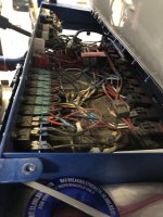
Okay, I’m just gonna throw this in here. This is how it looks after you have given up and said fuck it, nobody’s gonna look under here anyway. And I just want to get the damn thing running and wheel!
We start with the best intentionsOkay, I’m just gonna throw this in here. This is how it looks after you have given up and said fuck it, nobody’s gonna look under here anyway. And I just want to get the damn thing running and wheel!
Why so many relays ?Okay, I’m just gonna throw this in here. This is how it looks after you have given up and said fuck it, nobody’s gonna look under here anyway. And I just want to get the damn thing running and wheel!
Well, heater, lights, rock lights, fuel pump, engine bay lights, turn signals, tail lightsWhy so many relays ?
Well, heater, lights, rock lights, fuel pump, engine bay lights, turn signals, tail lights
I licensed it for the street.
.400 harness
17 wires
Rocklights
In-Cab front winch control (in and out)
USB port
Front LED pods (2 modes, amber and white)
Front LED light bar (2 modes, amber and white)
ECU power
Injectors + Coils power
Wake-up trigger to ECU
Fuel pump trigger to PDM
Starter solenoid
PDM ground
Stop light switch (power and trigger)
All properly sized and strain relieved.


It’s part of the building process.I see you using a small vice to hold one end as you build. Are you twisting the bundle after it's finished or as you put it together?
Certainly comes out very clean.
No, just naming random stuff under there. A couple of the relays aren’t being used. If you look on the left of the pic. There is a row of switches. So everything under there doesn’t run to a relay.You run stuff like blinkers and tail lights through a relay?
Found this while looking for some other stuff.Just to share this for ideas, not suggesting it's good for the OP's build but I always look at the OEMS for stuff I can repurpose.
This is power center for a excavator, these ratings are at 24v so not sure how that compares to 12, amps is amps right?
510-6341 fuse box, complete unit with fuses, buss bars, cover etc. $185
Fully sealed fuse compartments, not sure if actually waterproof though.


I haven't had the balls to try it.Will the ECU or smart electronics get messed up if the battery is disconnected but the alternators are still running and everything is still on?
Depends what electronics and how it's getting disconnected.Will the ECU or smart electronics get messed up if the battery is disconnected but the alternators are still running and everything is still on?
Got me thinking about what order to shutdown with the kill switch.Depends what electronics and how it's getting disconnected.
But the load dump from an alternator has been know to fry a thing or 2
The stock 2010 truck alternator has a small two pin plug that is on the ECU harness. Will that cause any back feeding? Alt main power lug only goes to winch and kill switch where it contacts to battery when on.Kill ECU first as long as there are no path to alternator backfeeding once that leg is disconnected.