WaterH
Well-known member
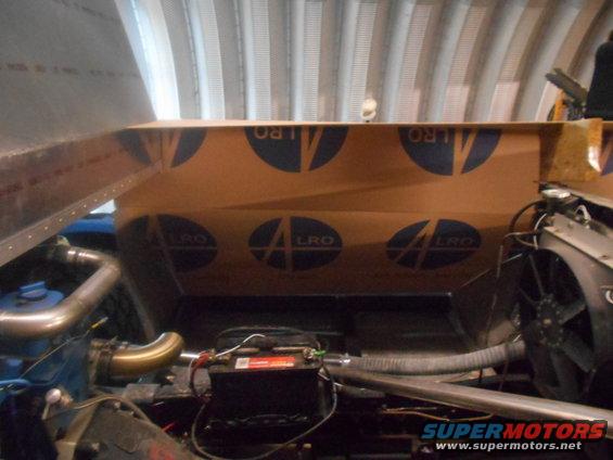
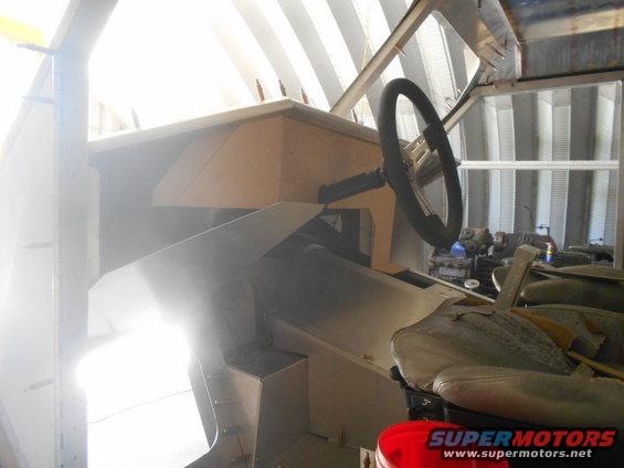
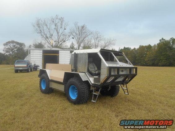
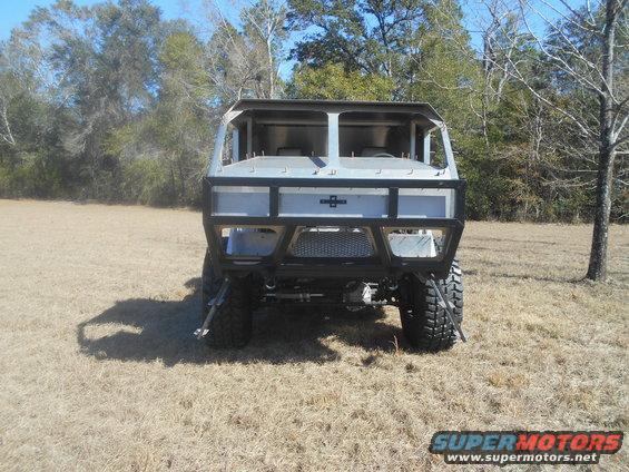
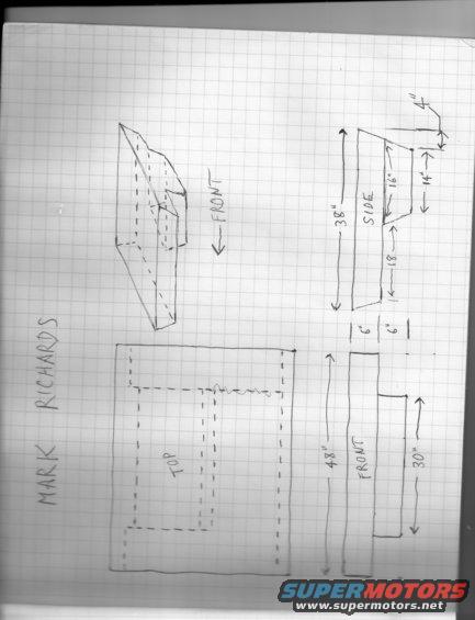
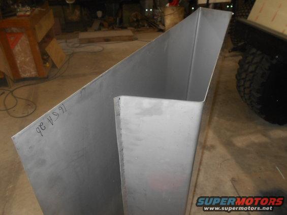
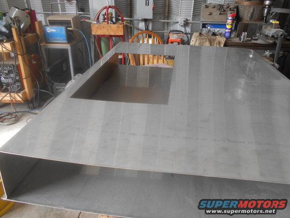
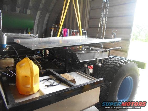
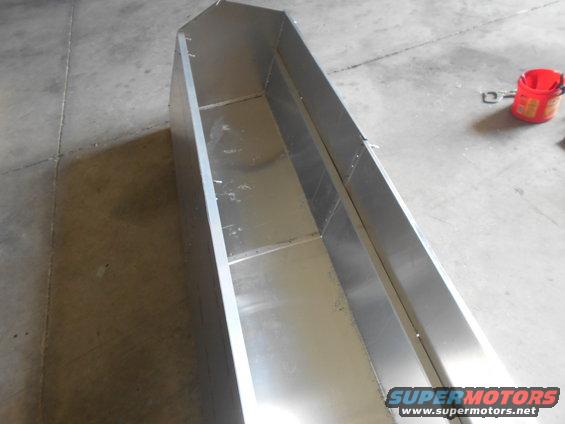
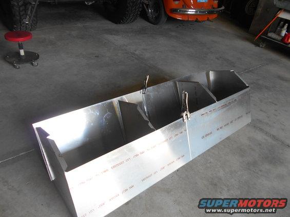
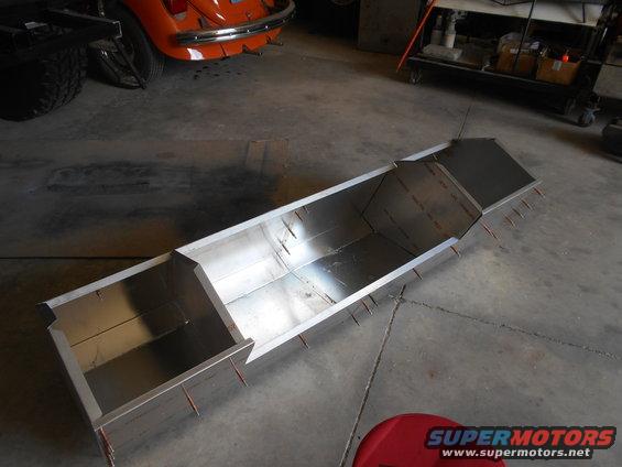
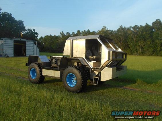
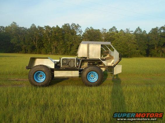
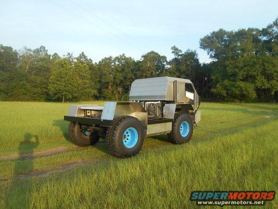
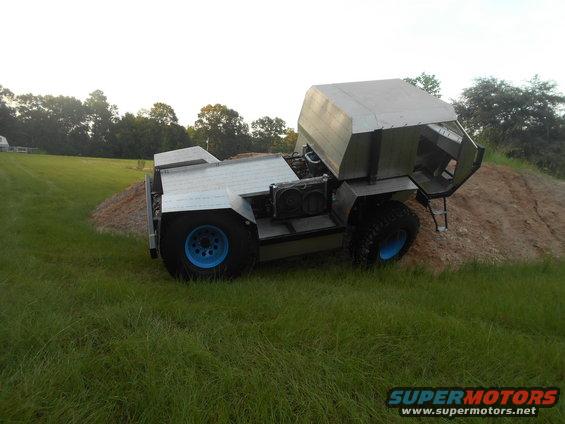
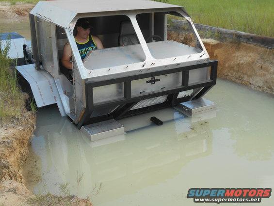
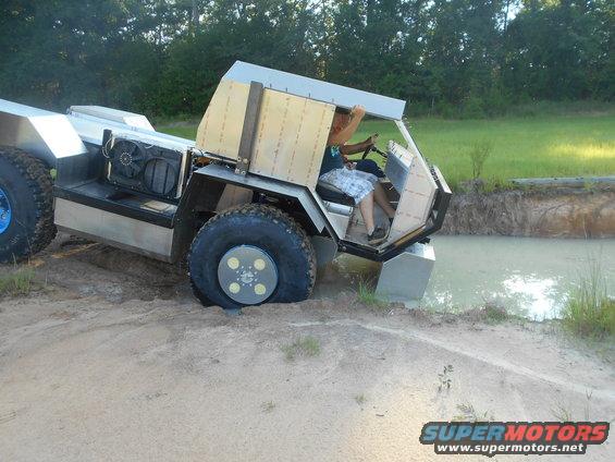
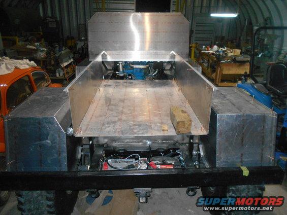
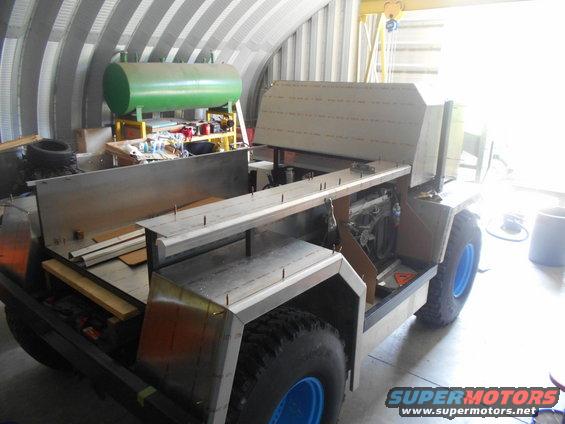
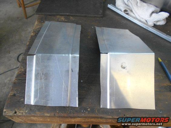
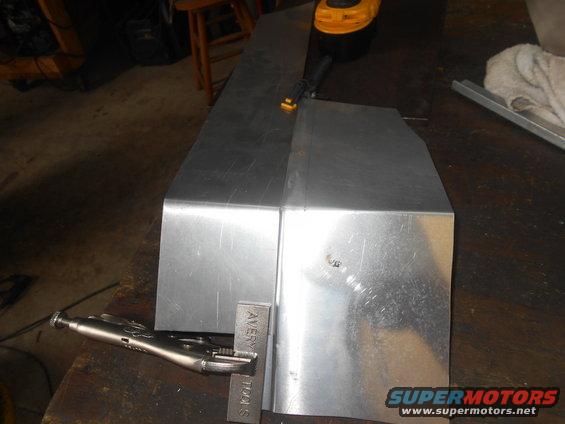
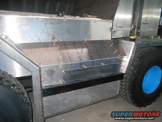
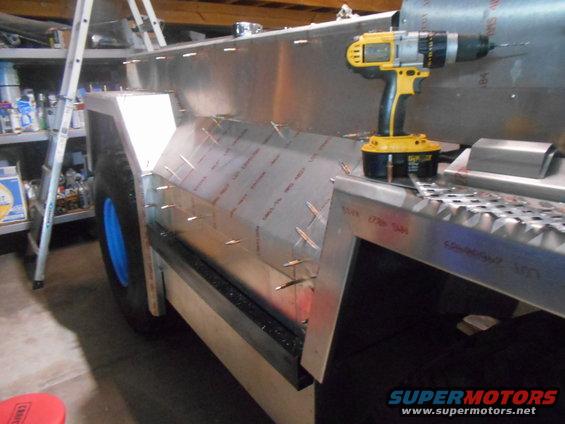
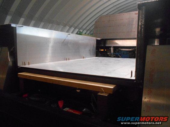
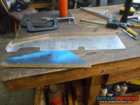
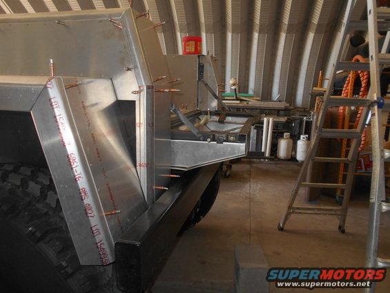
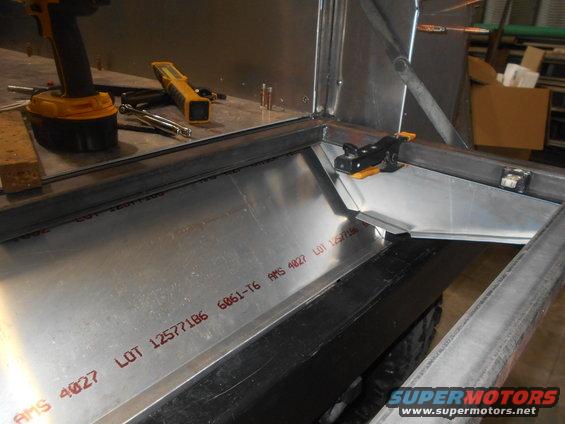
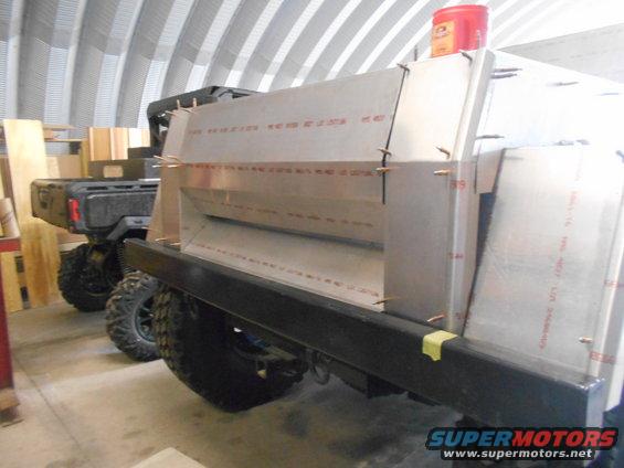
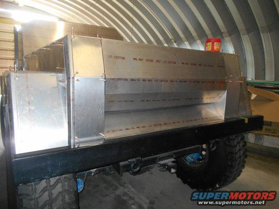
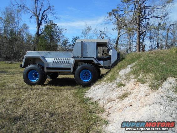
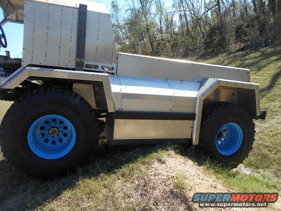
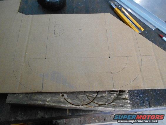
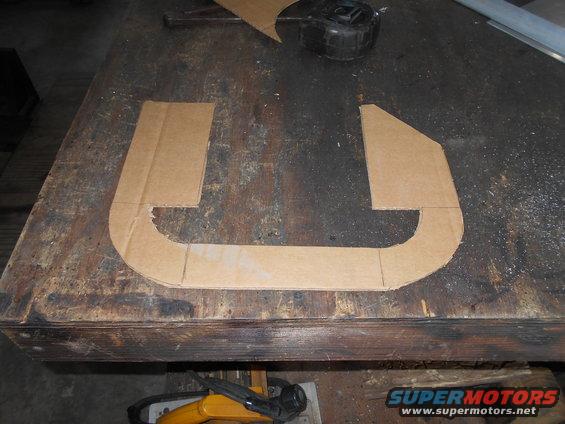
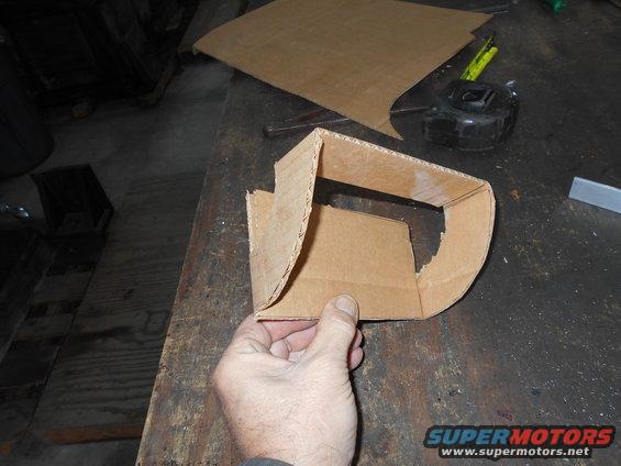
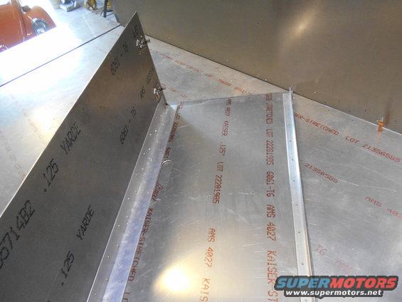
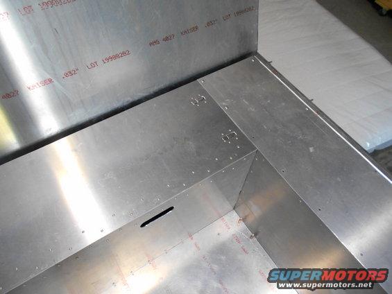
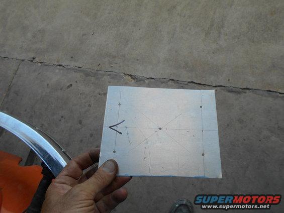
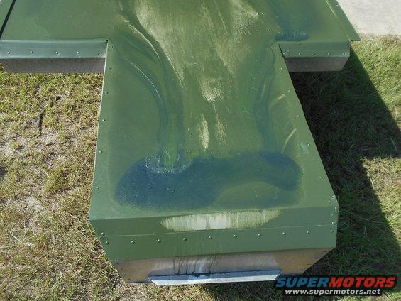
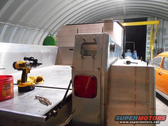
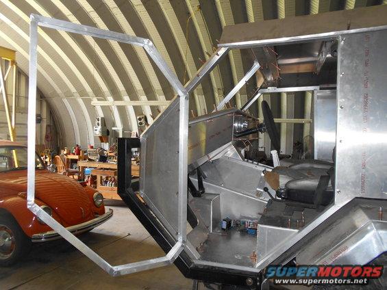
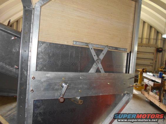
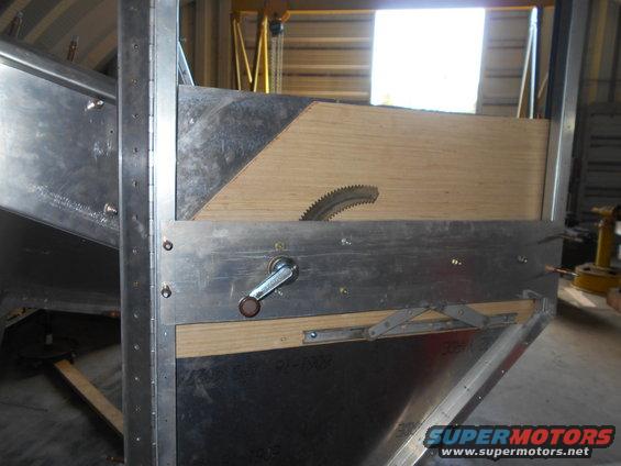
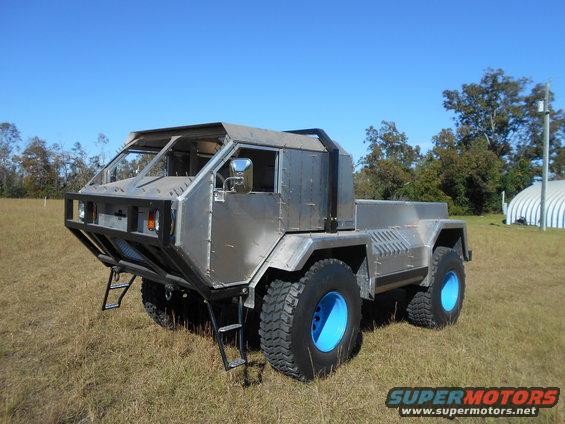
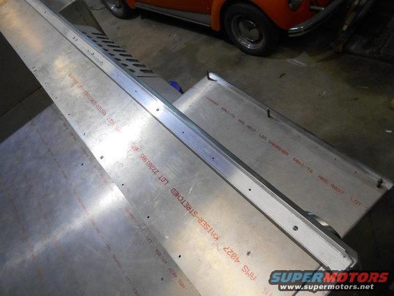
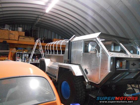
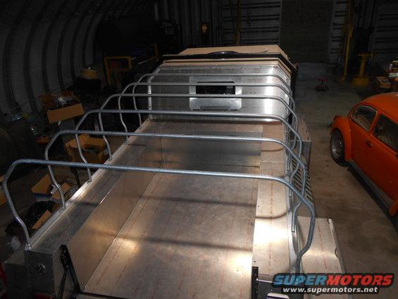
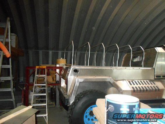
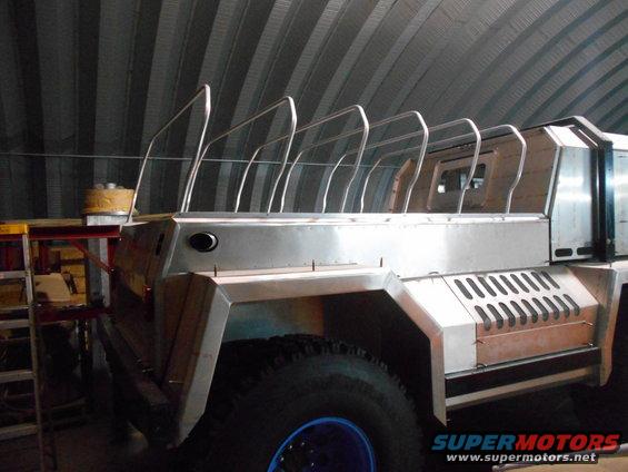
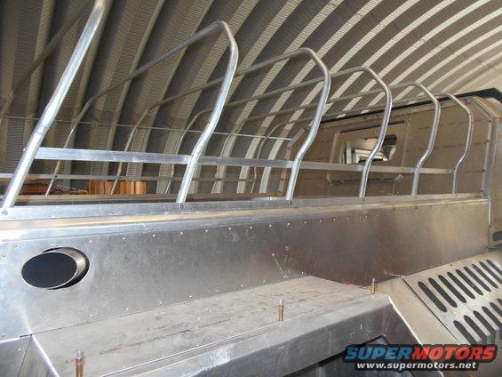
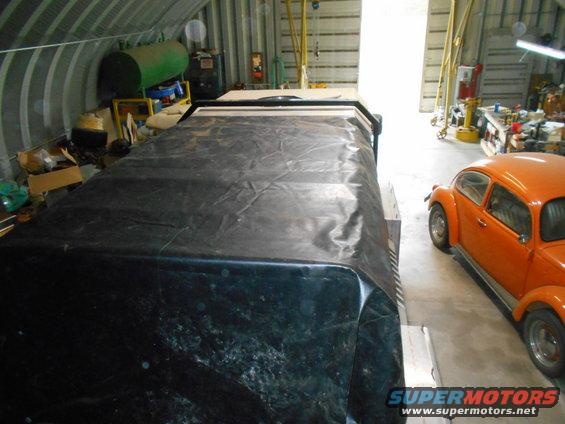
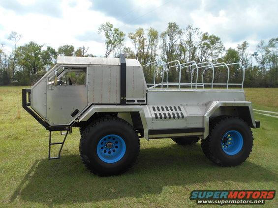
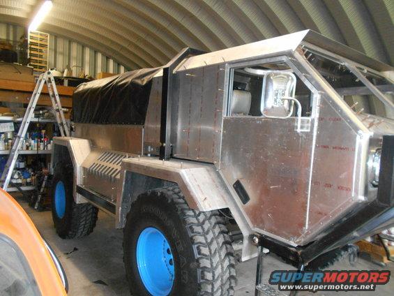
I had these pics of some cardboard bed sides for awhile. I forgot to post em. I planed to pull it outside, but got tangled up in the console/dash. It's kind of hard to see in the garage. But you can get an idea.
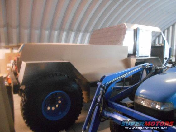
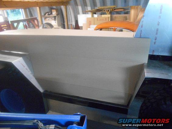
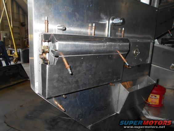
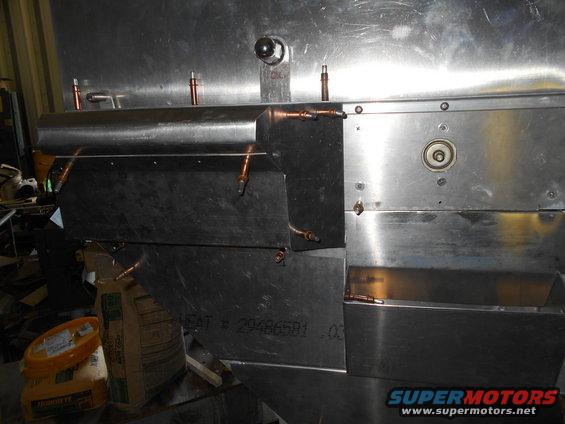
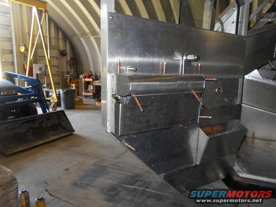
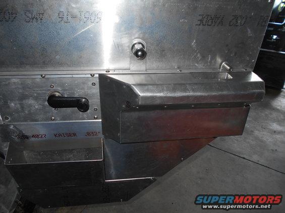
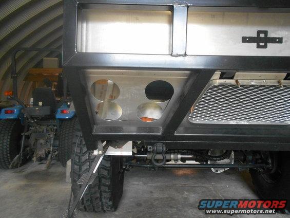
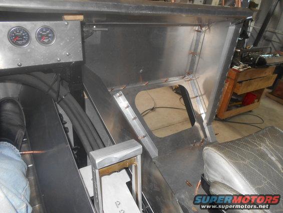
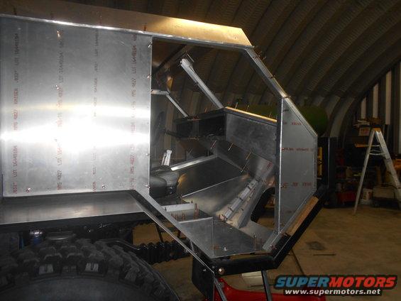
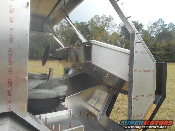
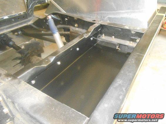
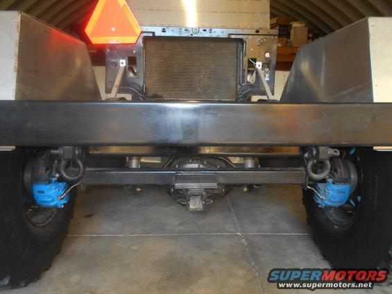
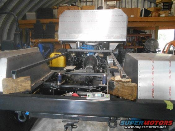
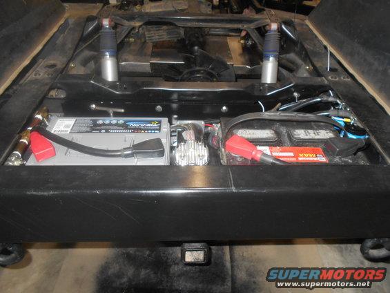
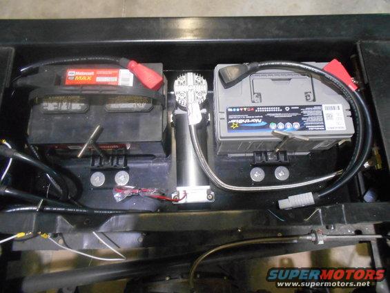
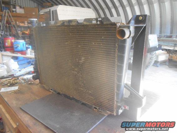
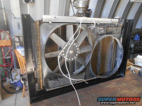
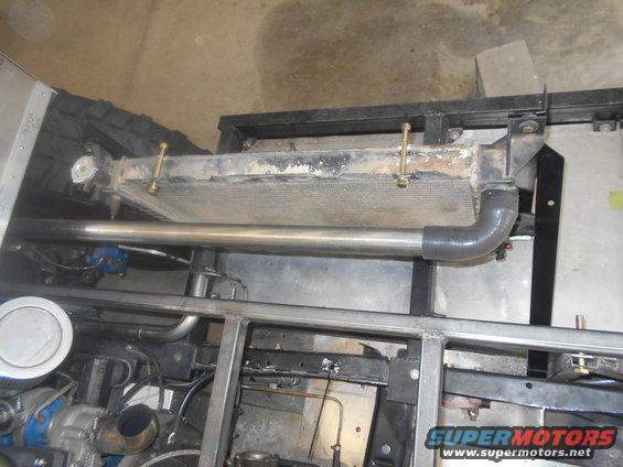
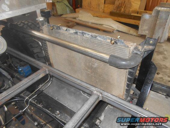
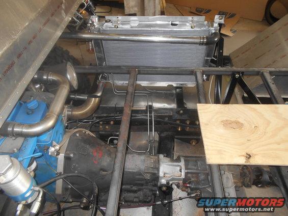
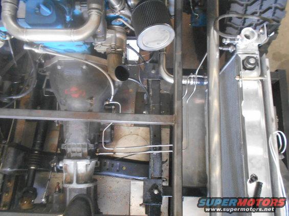
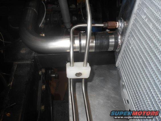
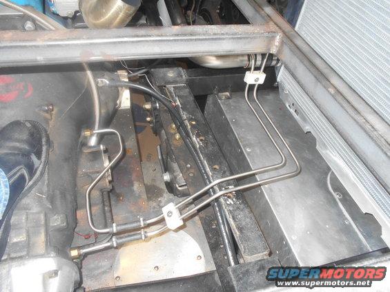
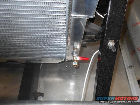
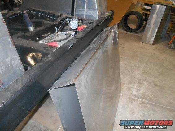
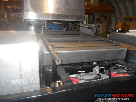
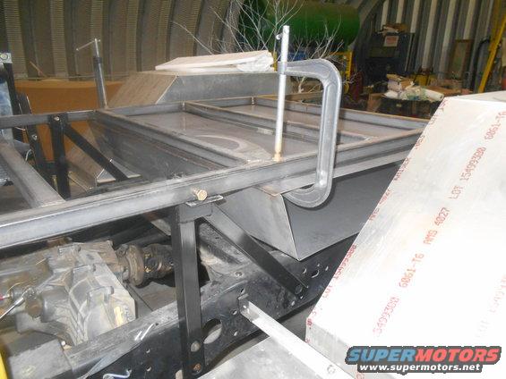
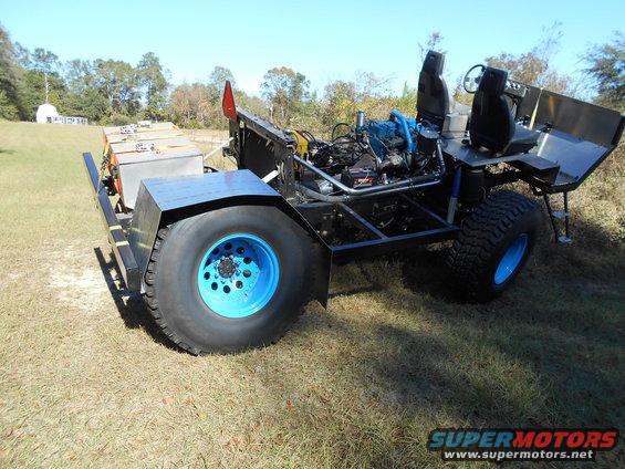
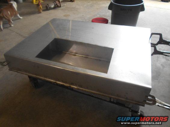
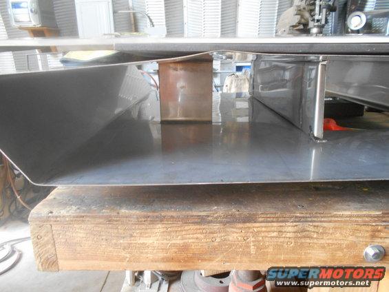
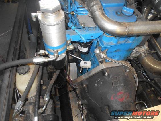
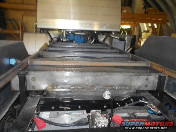
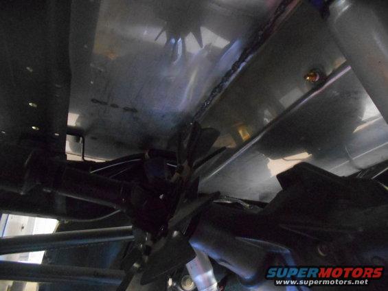
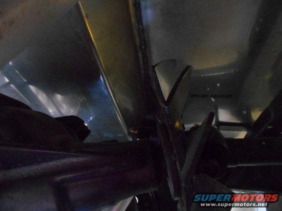
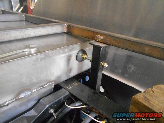
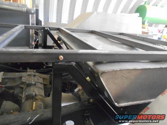
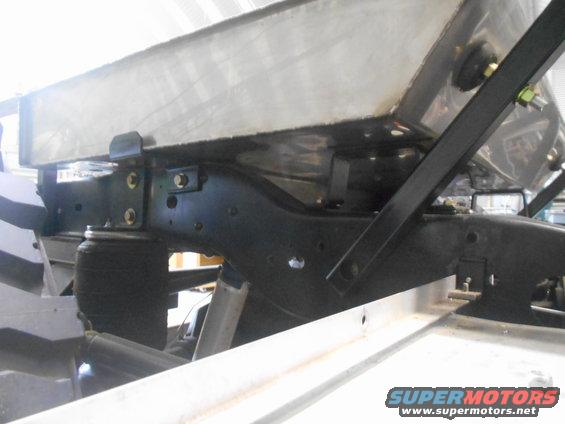
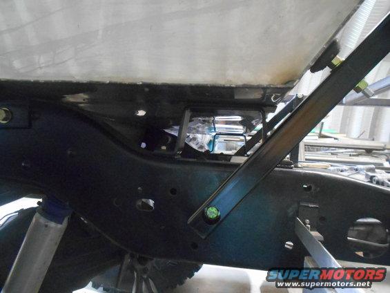
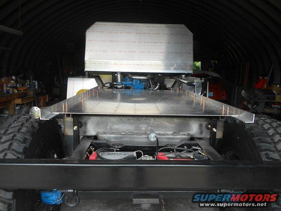
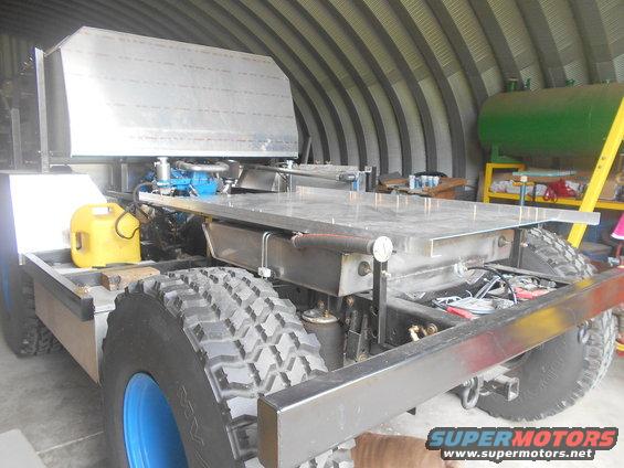
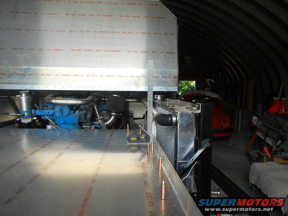
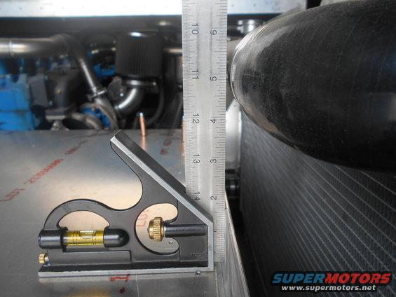
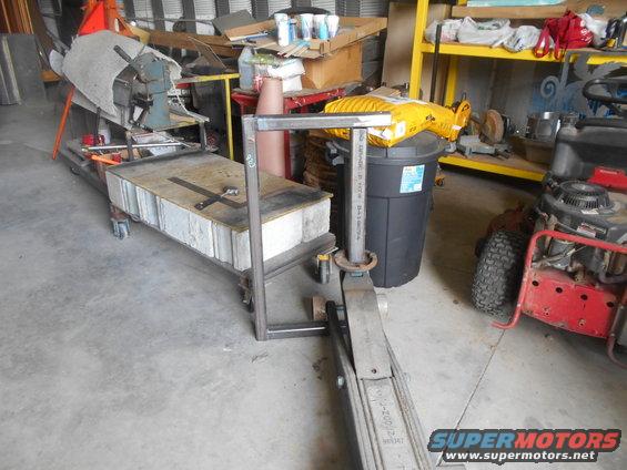
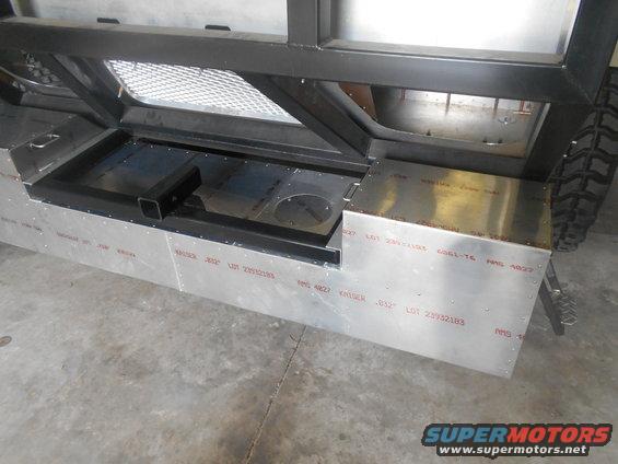
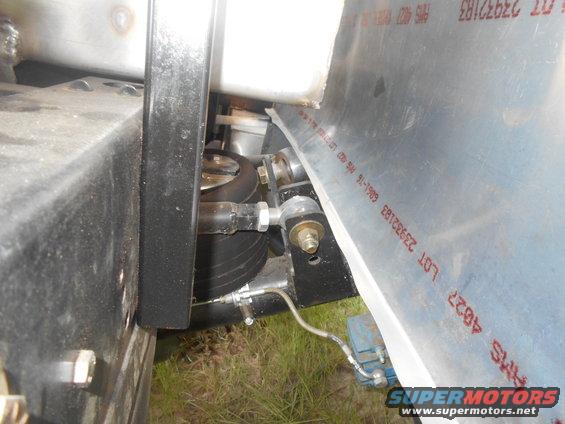
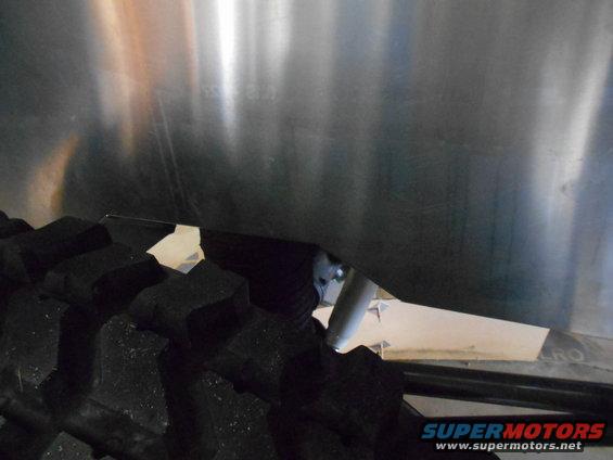
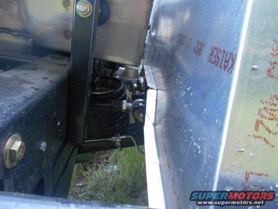
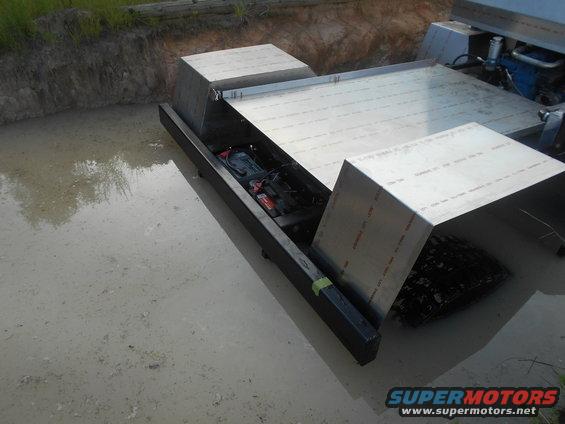
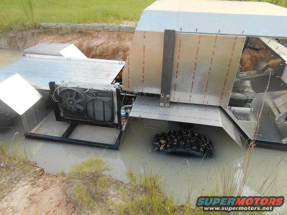
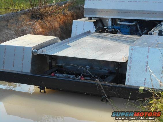
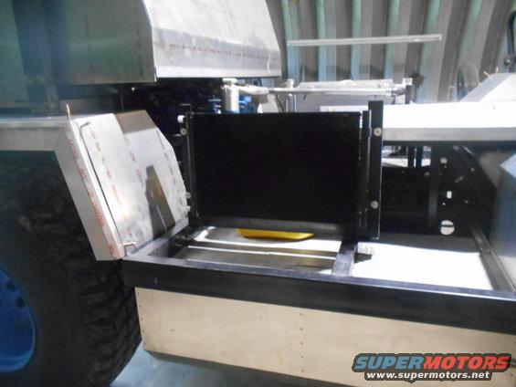
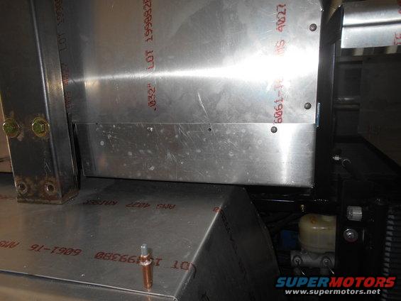
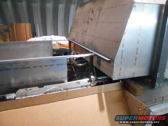
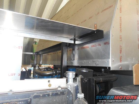
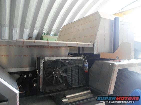
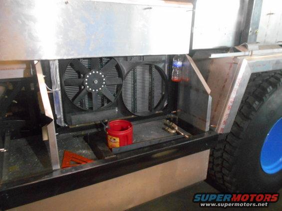
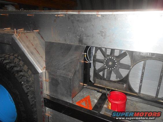
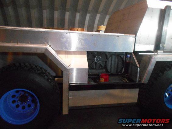
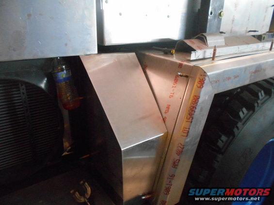
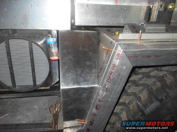
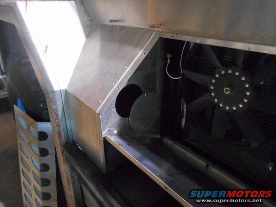
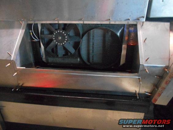
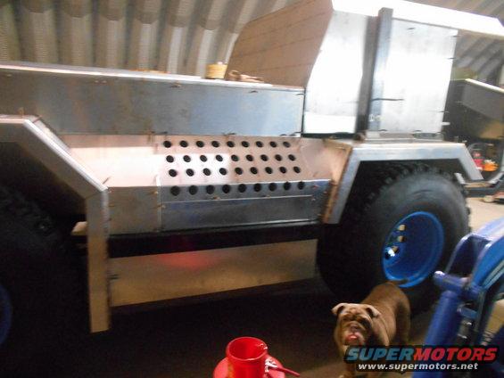
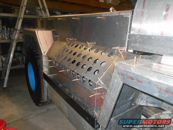
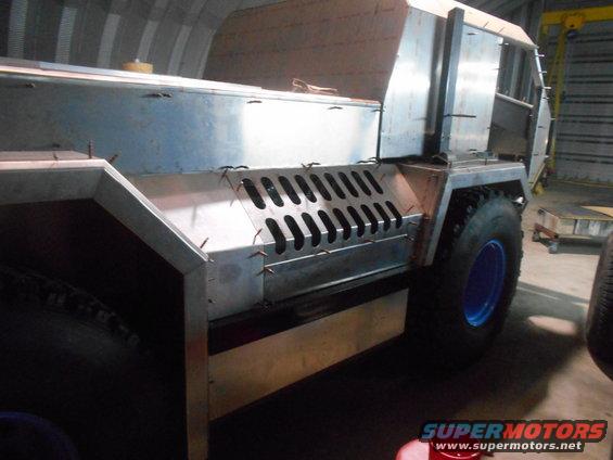
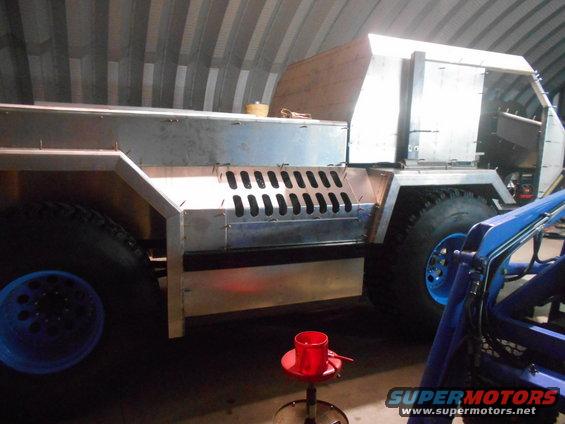
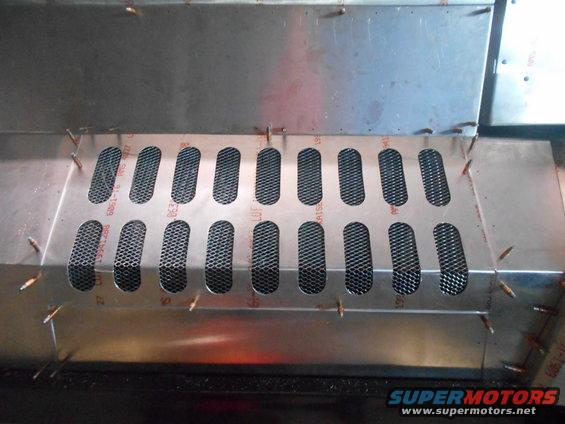
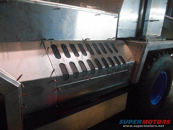
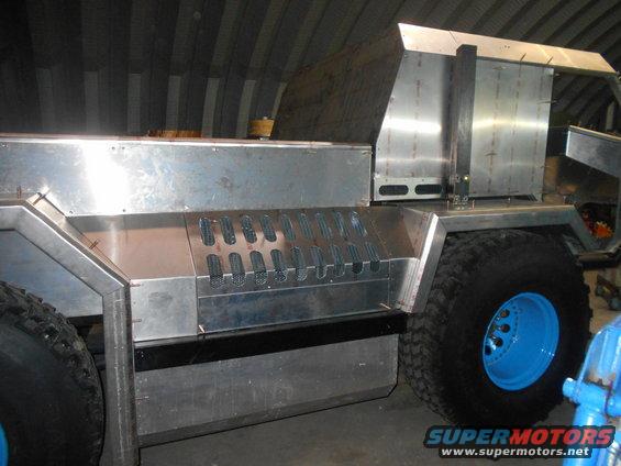
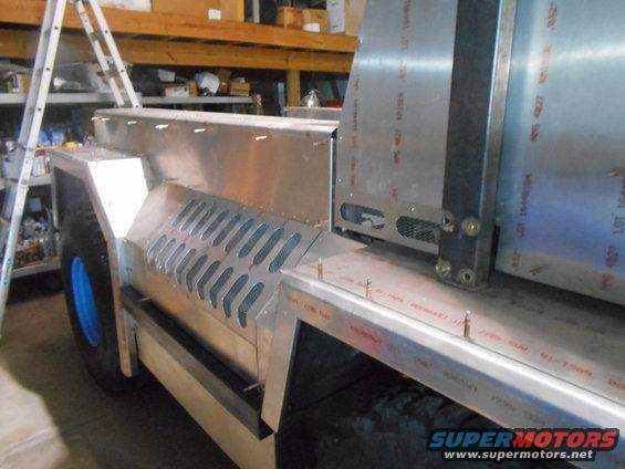
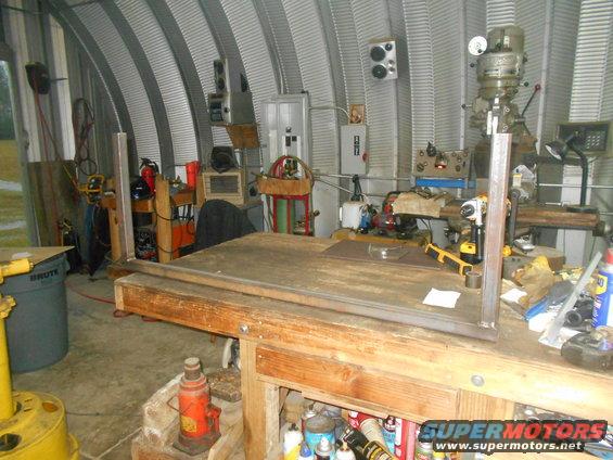
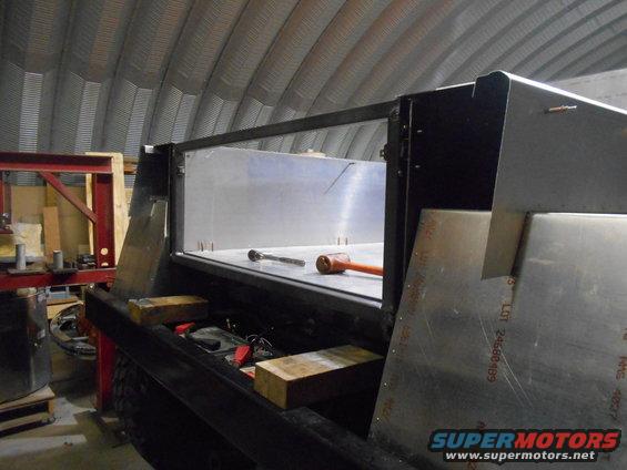
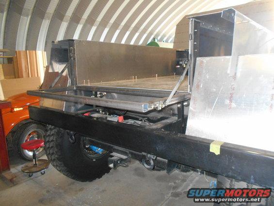
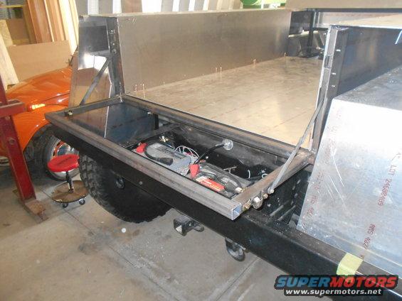
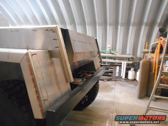
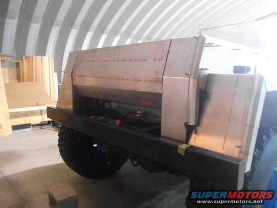
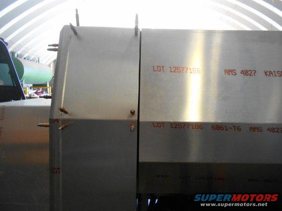
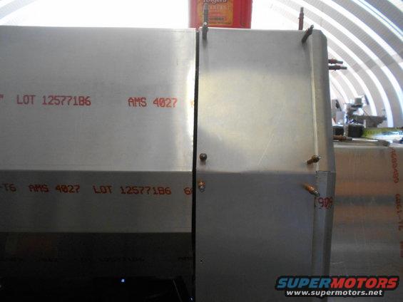
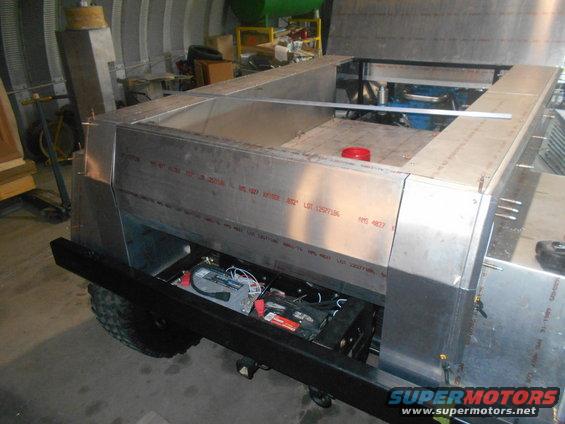
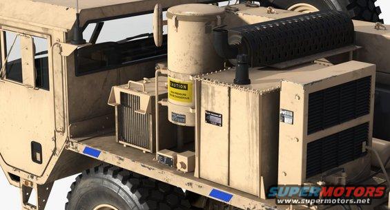
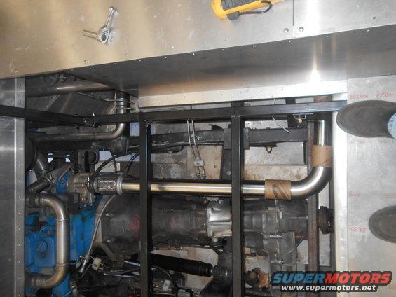
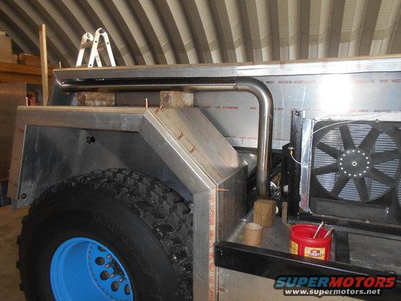
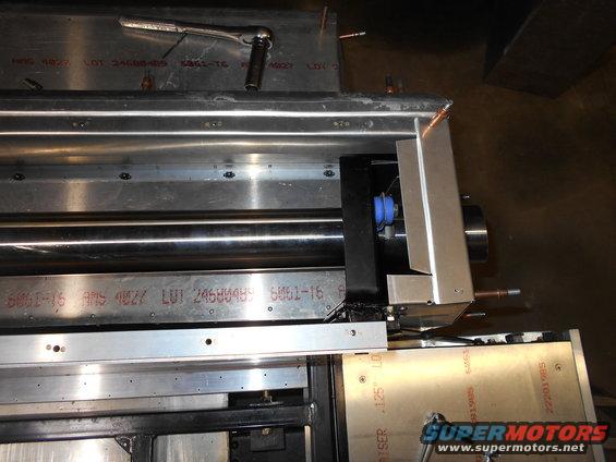
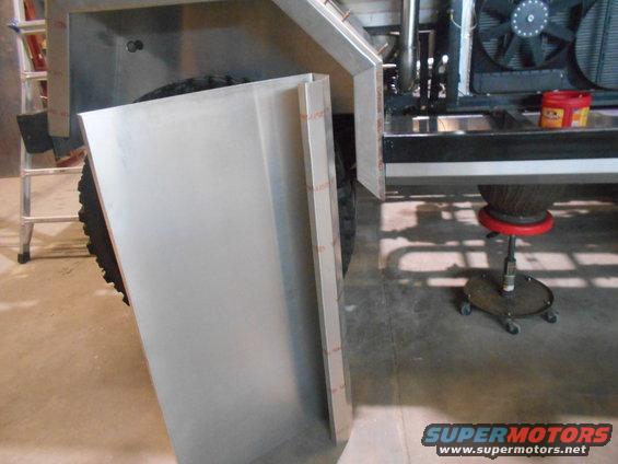
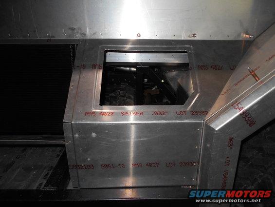
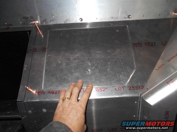
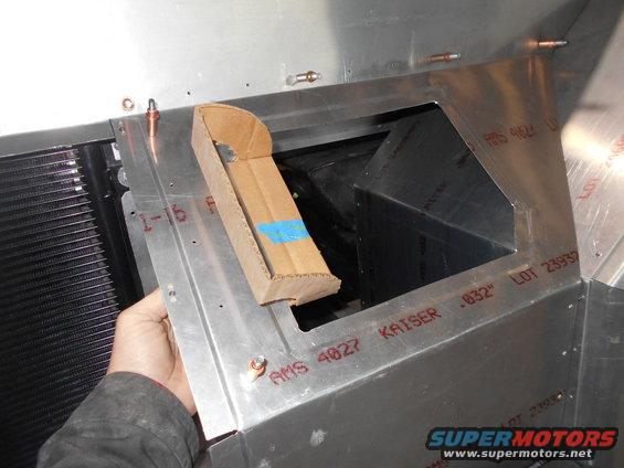
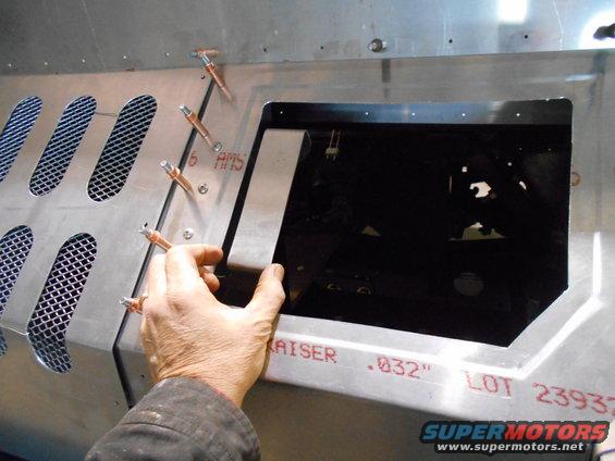
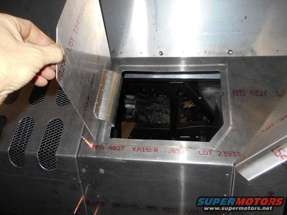
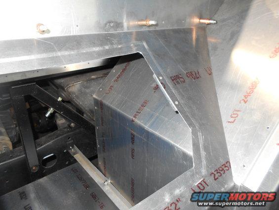
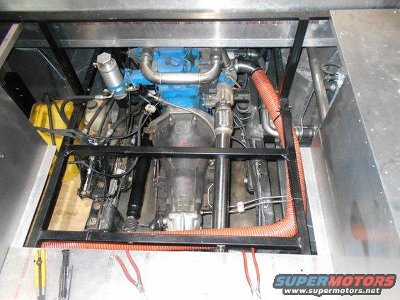
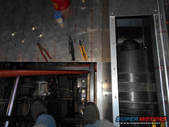
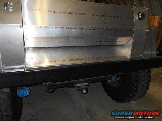
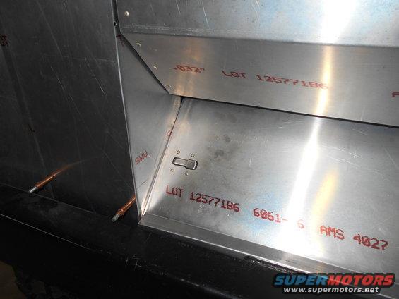
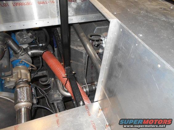
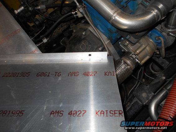
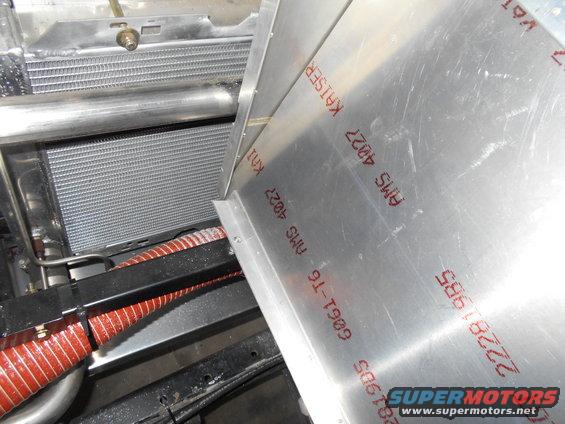
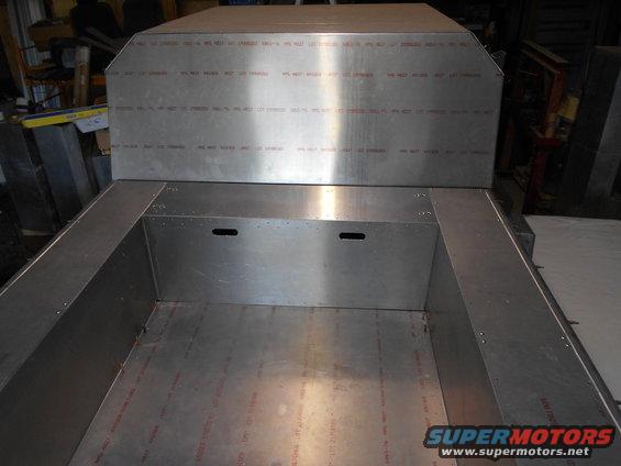
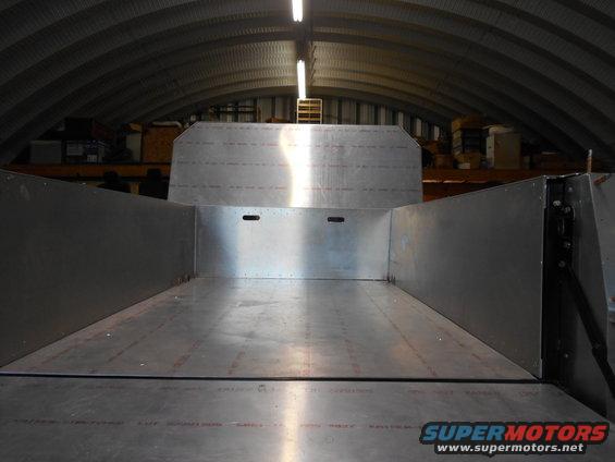
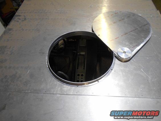
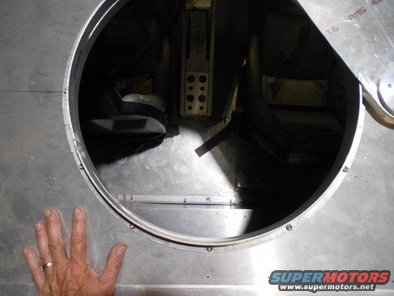
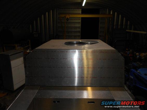
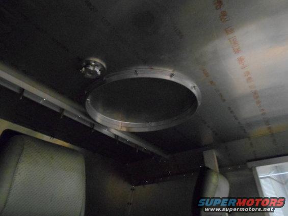
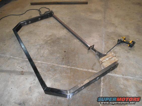
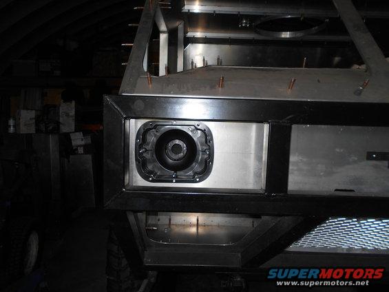
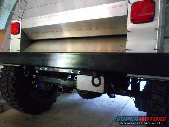
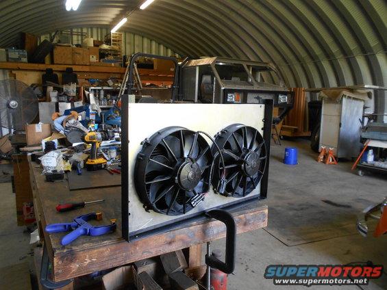
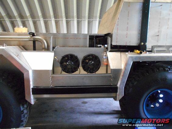
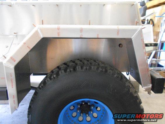
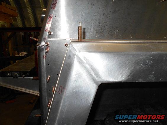
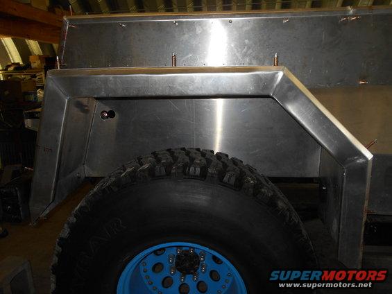
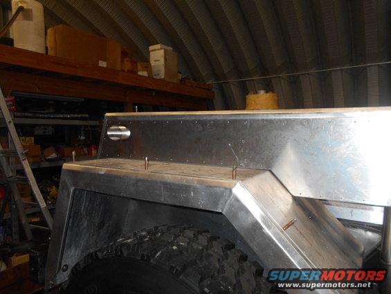
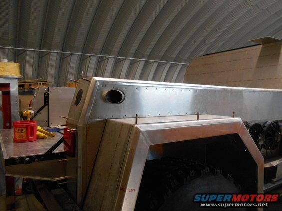
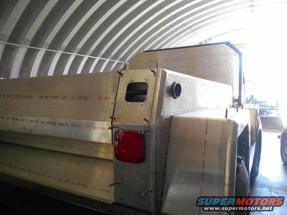
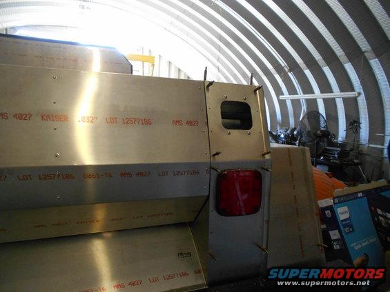
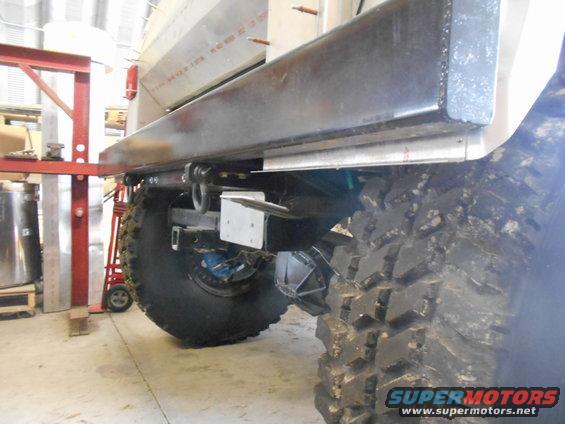
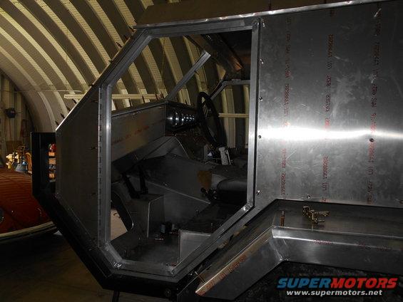
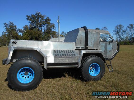
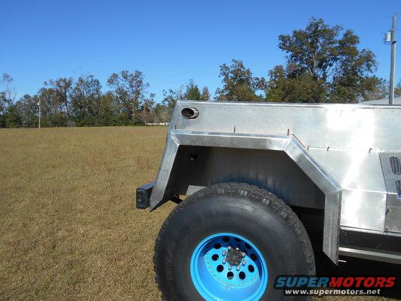
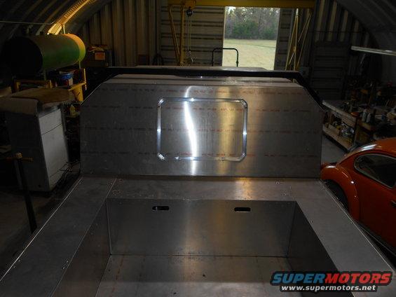
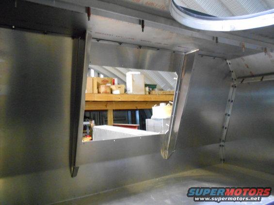
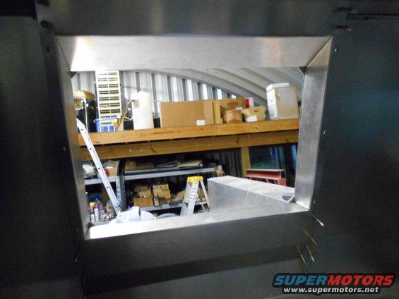
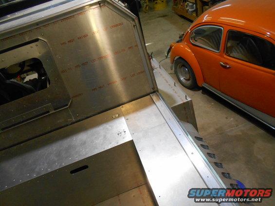
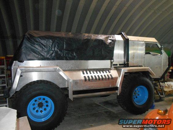
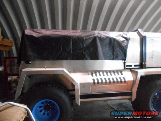
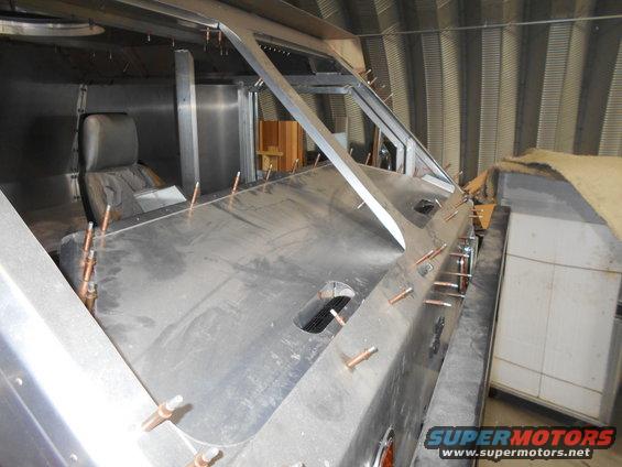
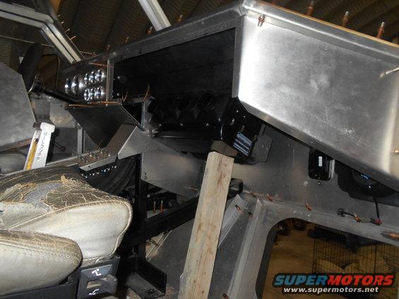
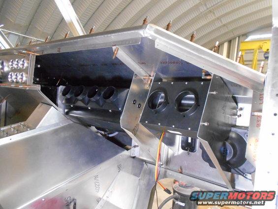
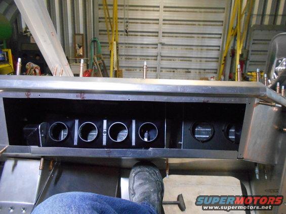
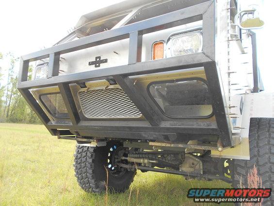
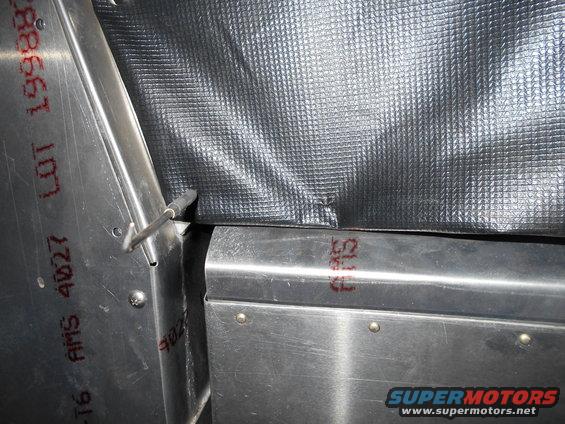
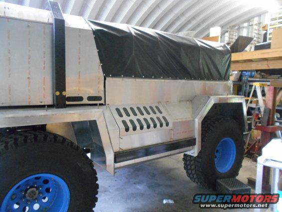
Before I can work on this part I have to relocate the radiator. It will go in the side. Here you can see there should be room in there.
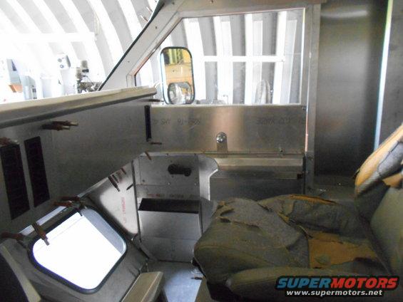
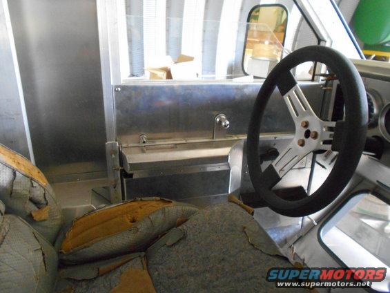
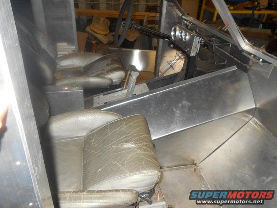
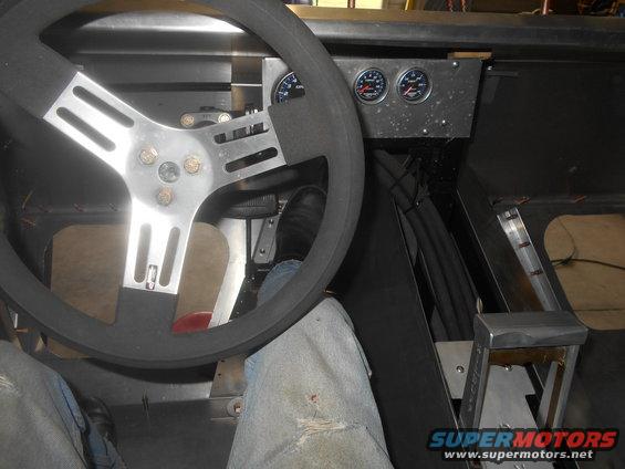
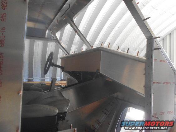
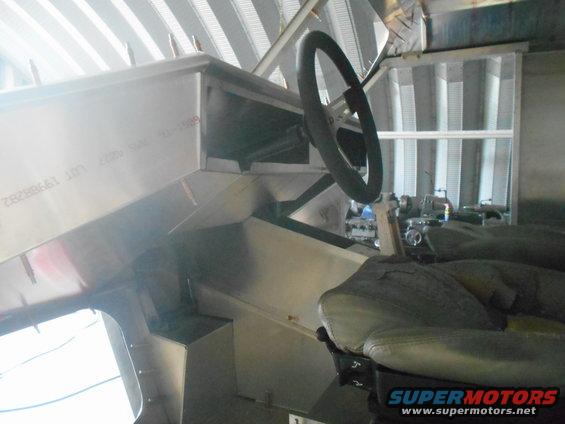
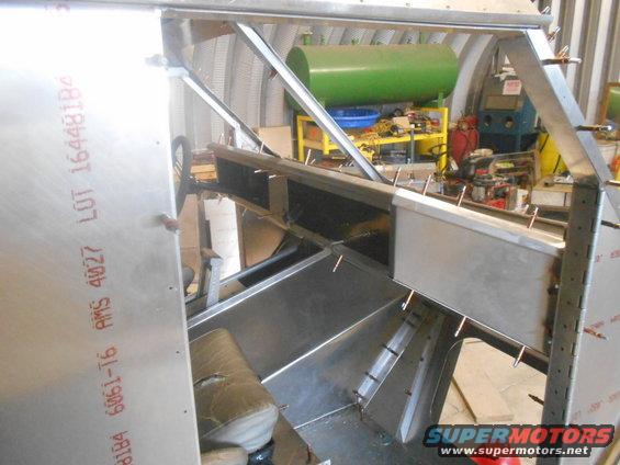
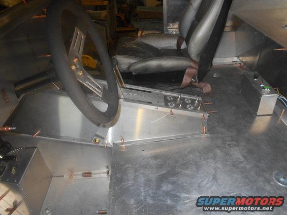
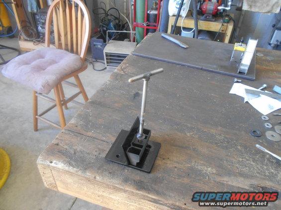
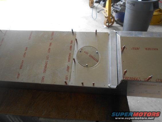
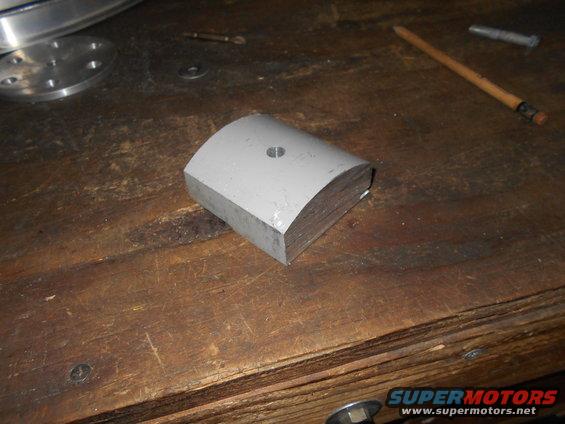
But I'm having fun with the console/dash right now. Here I made a little riser to get the shifter in place.
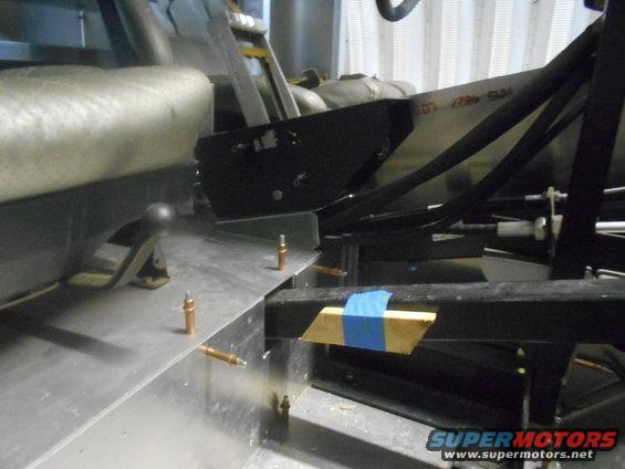
I had to make the driver's side of the console in two pieces.
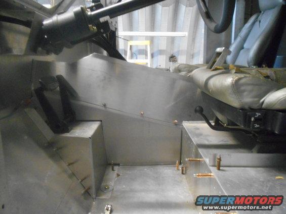
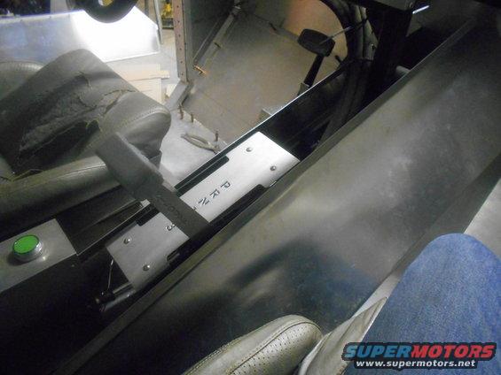
Still needs lots of work, but I like it.
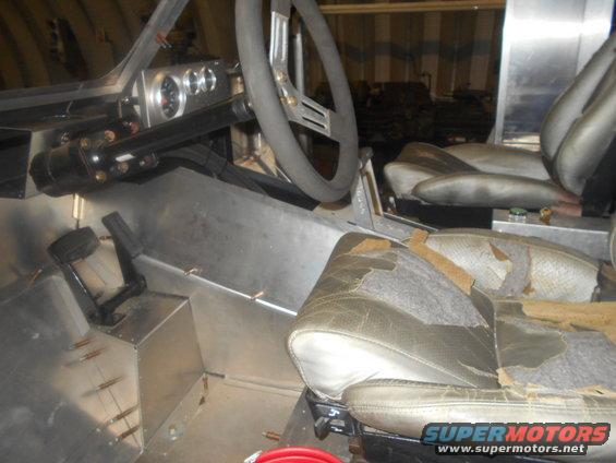
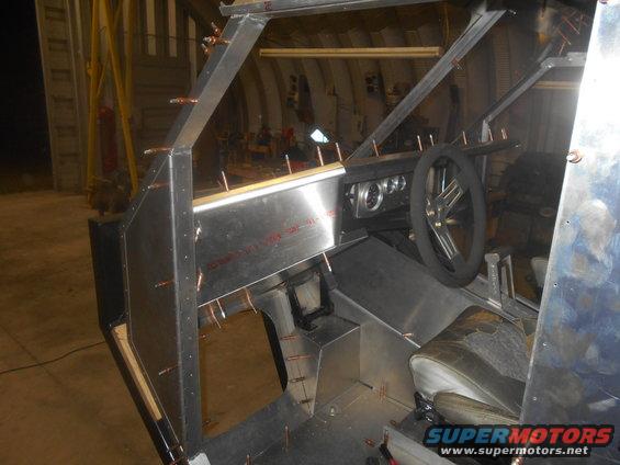
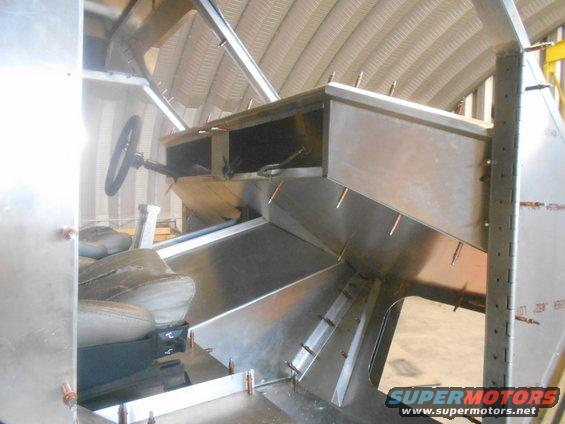
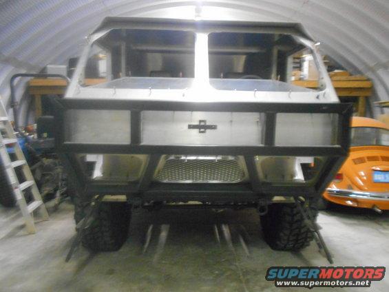
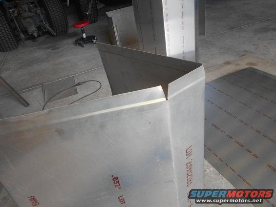
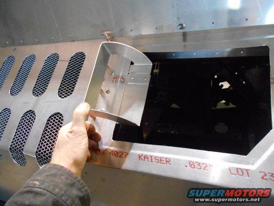
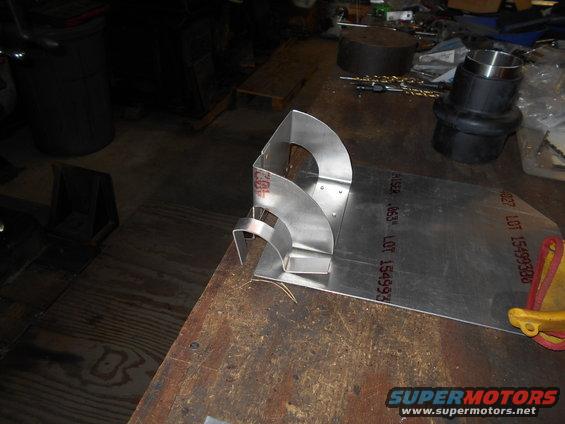
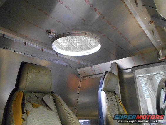
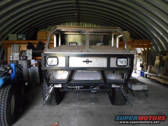
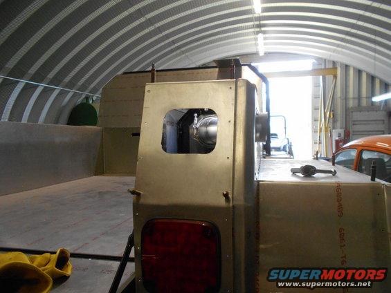
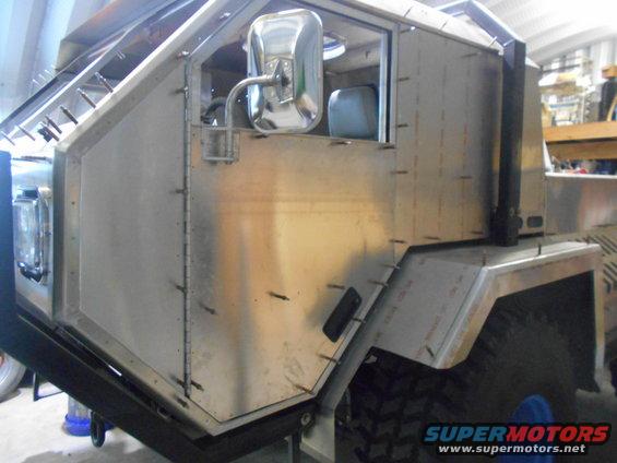
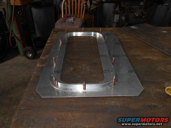
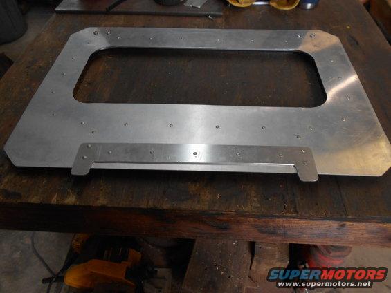
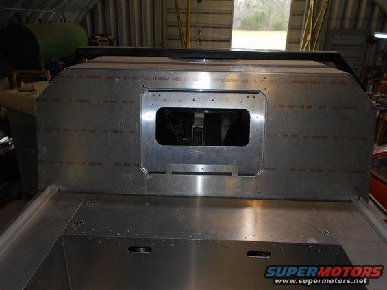
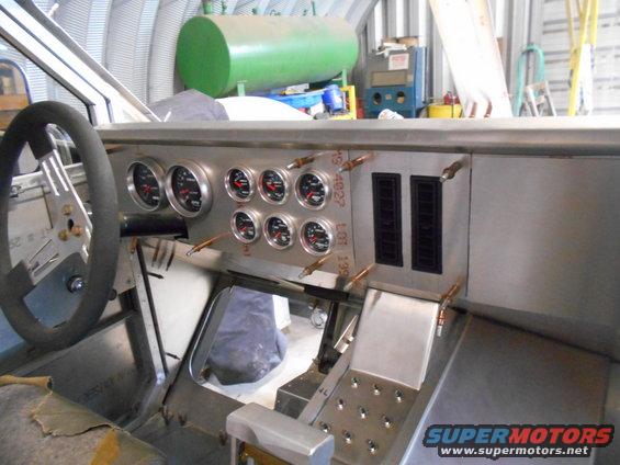
I got some progress to report on the dash. First, I made a glare shield.
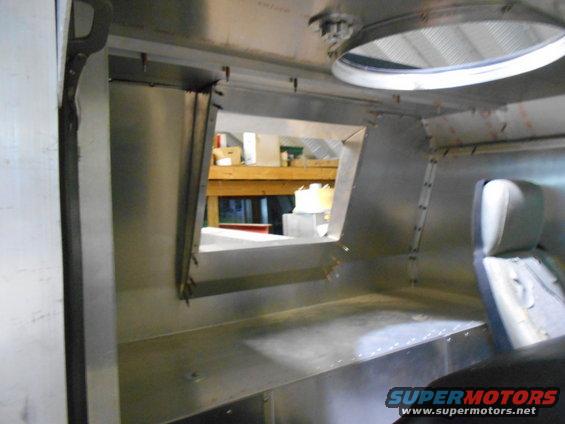
I wanted this to shield the sun from reflecting off the lower windows. So I figured I should cut the lower windows.
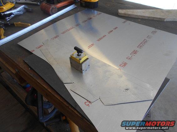
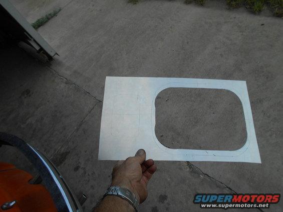
I played with some cardboard to make a dash that wouldn't interfere with my line of sight to the lower windows.
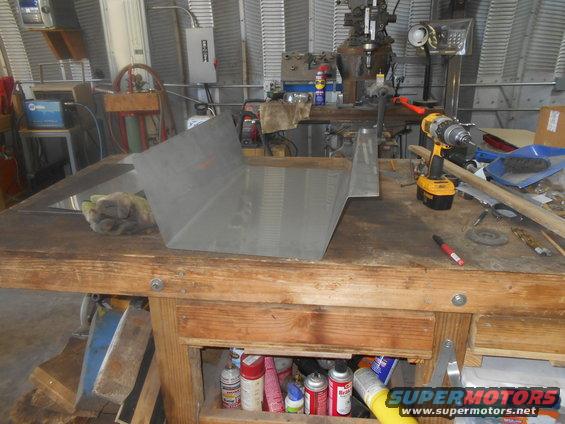
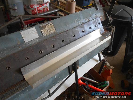
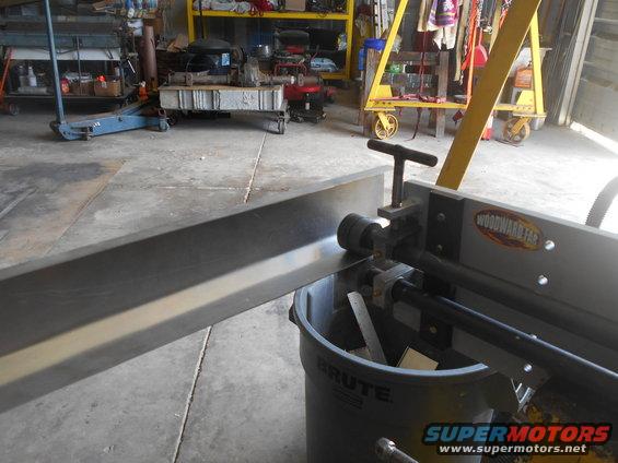
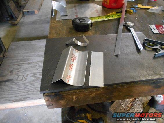
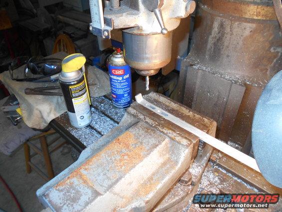
Than I got to cutting metal.
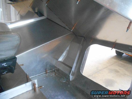
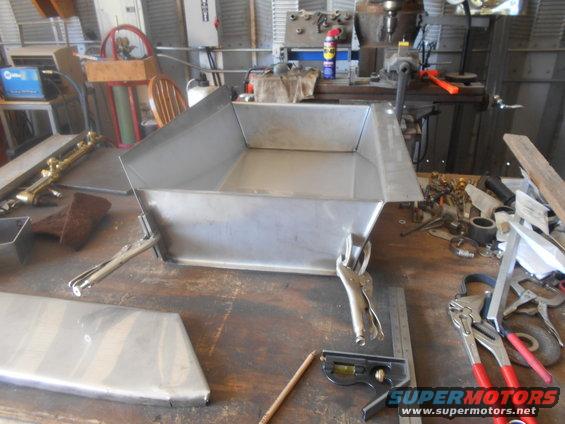
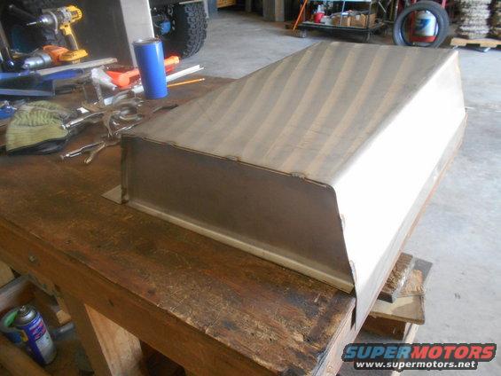
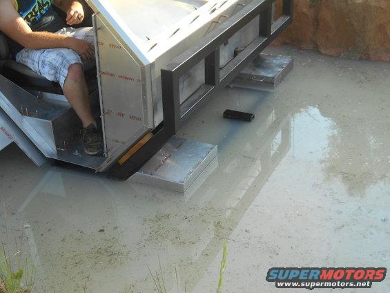
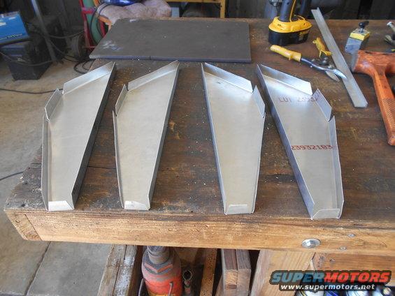
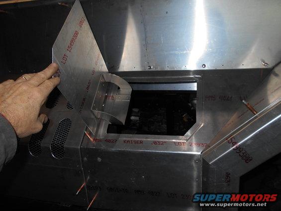
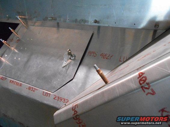
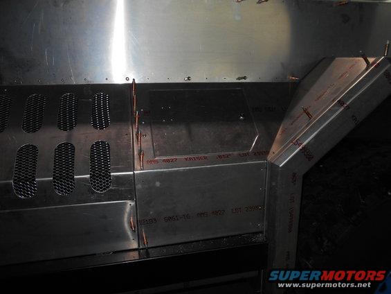
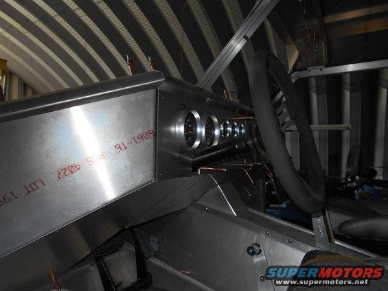
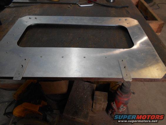
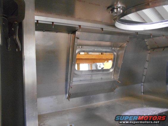
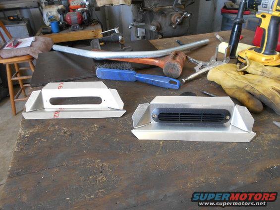
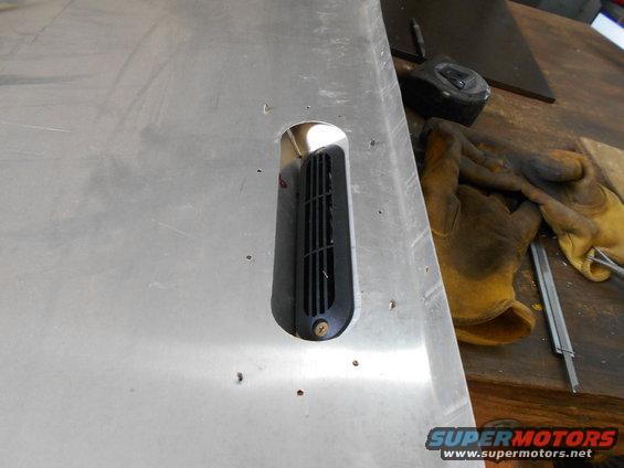
Because the truck is so high, it's easy to see under the dash when standing outside. I couldn't leave the "underdash" open, so I made lower covers.
Continued
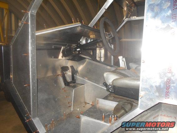
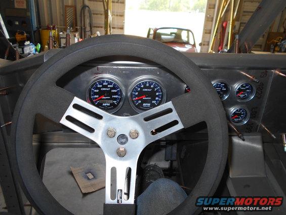
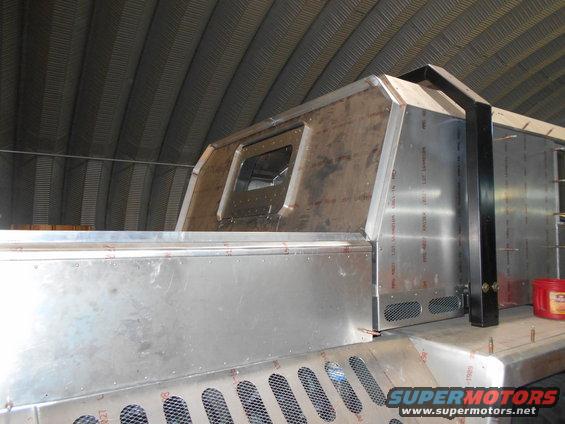
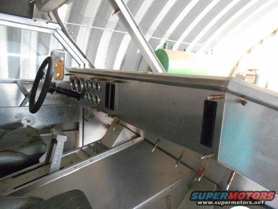
So after getting most of the dash clecoed together, it really got strong. It will even be stronger after finel riveting. I'm glad because you have a tendency to grab it when climbing in.
I might even put a pocket on the edge to hook your fingers in.
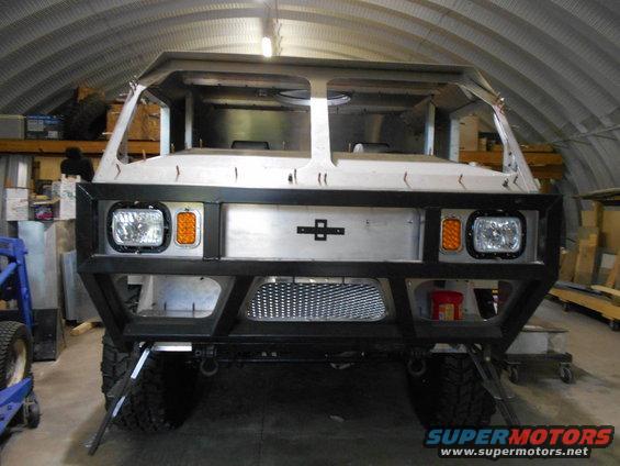
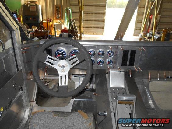
I like the way the glare shield looks from the front. I hope it can be seen after the windshield is in.
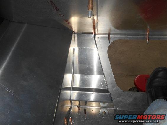
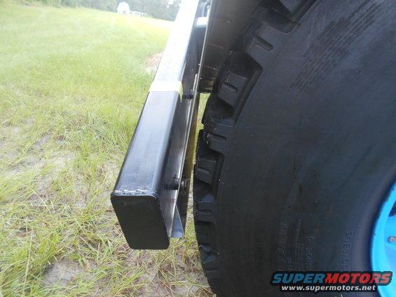
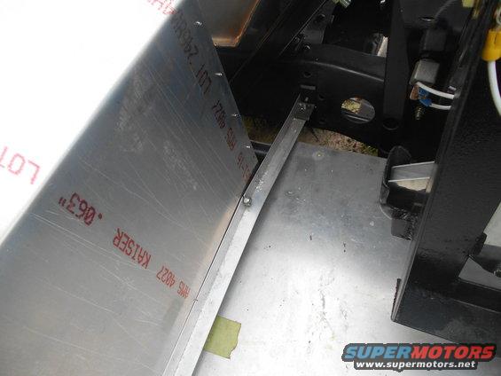
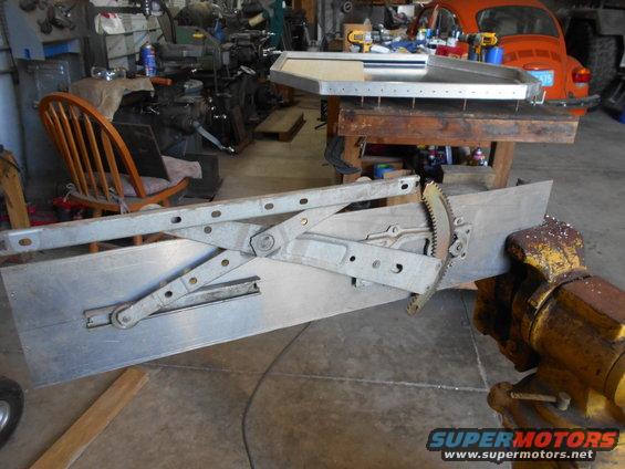
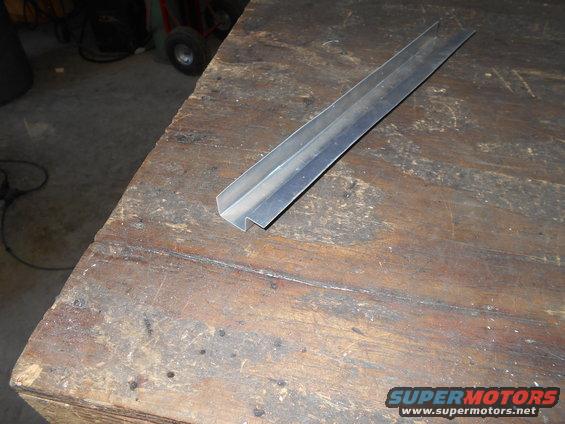
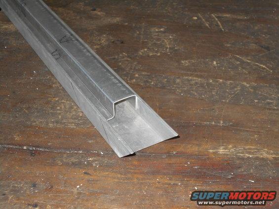
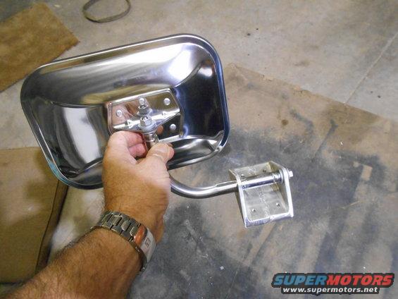
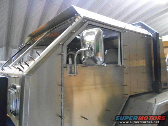
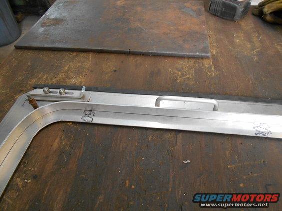
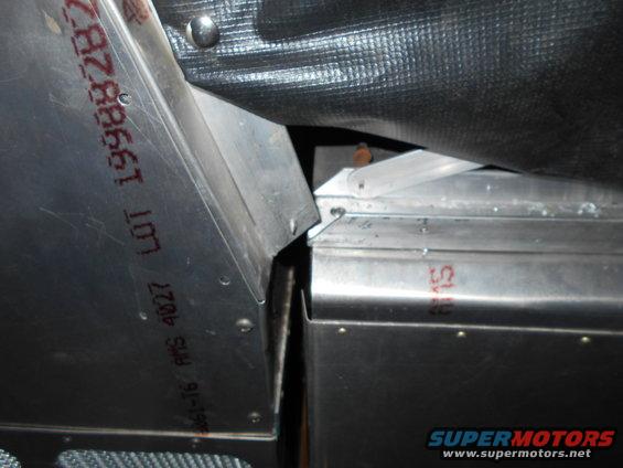
On another note, you might have noticed the angle aluminum on the pax side kick panel. I put this in to give some extra strength next to the glass. (The driver's side has the raised pedal section)
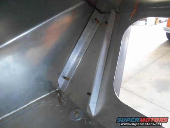
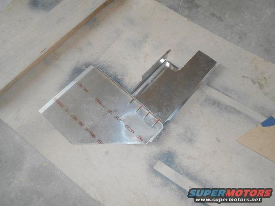
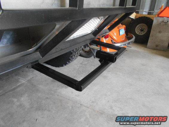
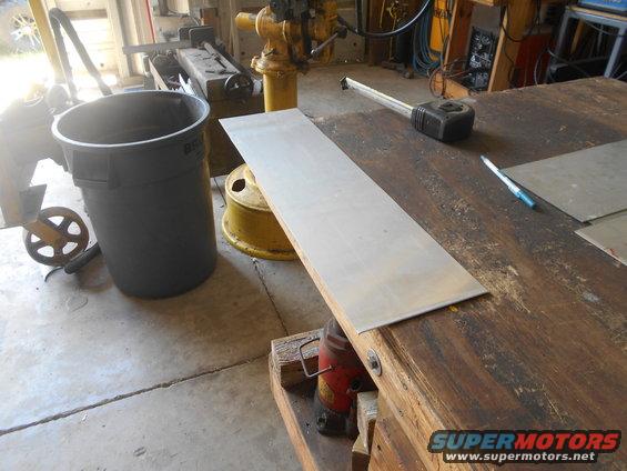
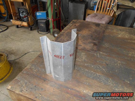
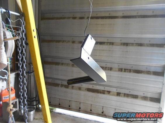
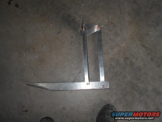
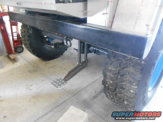
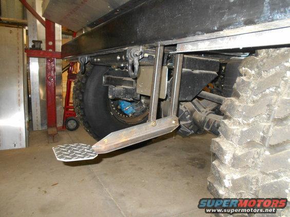
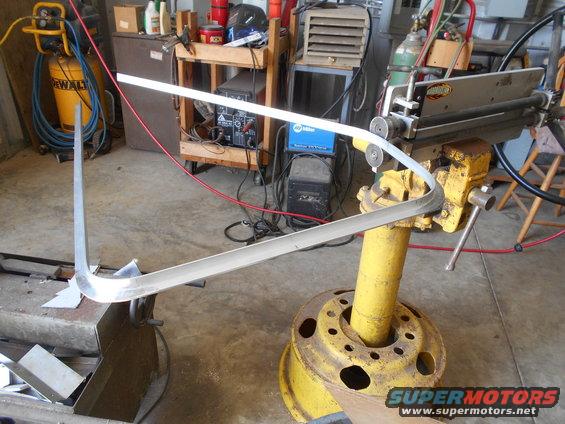
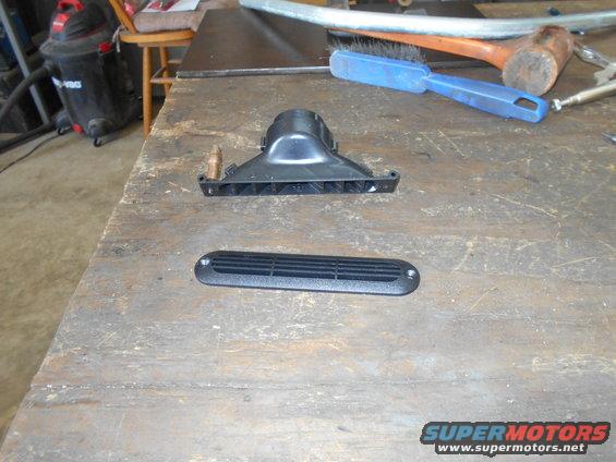
I was thinking I should make a foot pad so the pax has something to brace themselves in a exciting situation. Better than using the glass. LOL. Anyways took a day to make this.
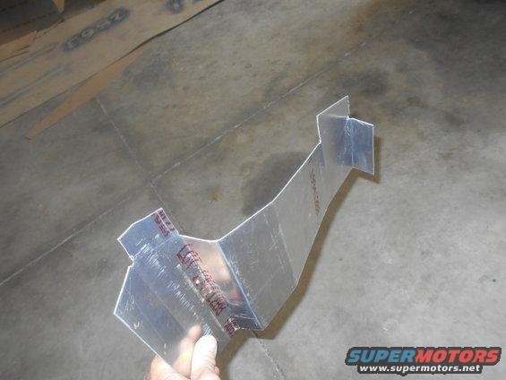
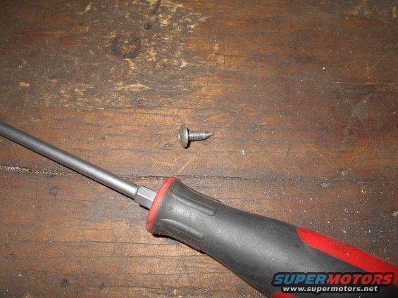
It's going to be attached with a couple screws, but it actually fits so tight that I have to pound it on.
Update,
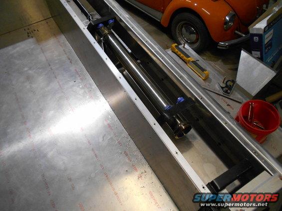
I never worked out a transfer case shifter, so time to through money and time at it. Since I had push-pull cables everything else, I went that route. I needed bracket on the t-case adapter to attach the cable sleeve. If you have followed this thread from the beginning, you know I swapped a aluminum adapter for a cast iron one. I like it, but for some reason they only put one threaded boss on the side for linkage to attach. (The aluminum one had two bosses) The problem with one is I had to make the bracket wrap around the casting so it won't be likely spin on the single bolt.
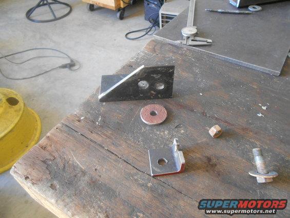
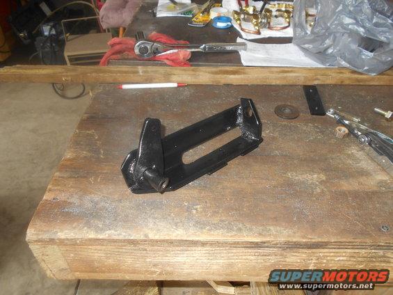
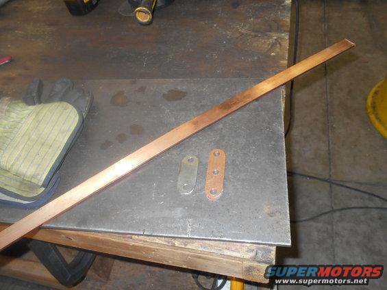
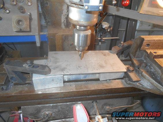
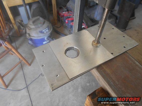
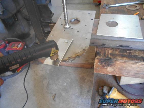
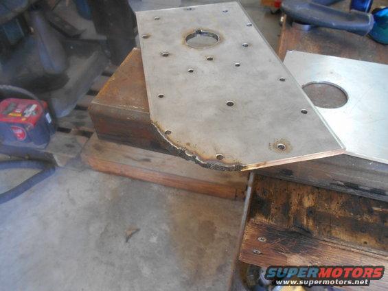
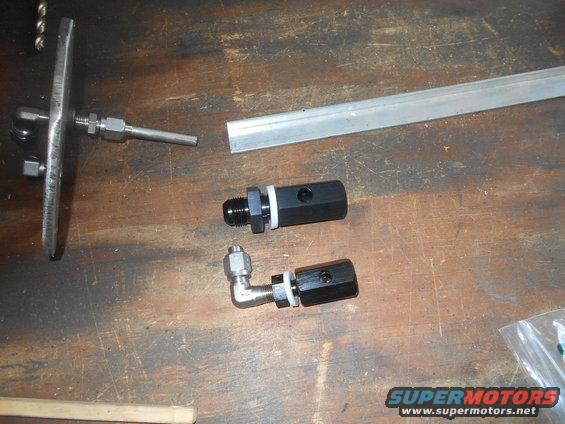
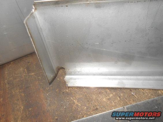
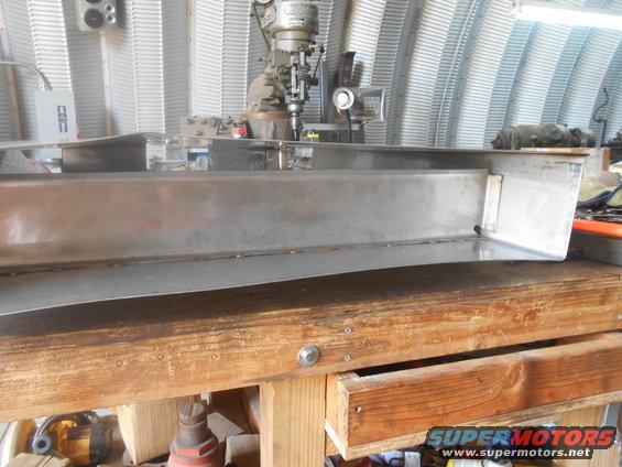
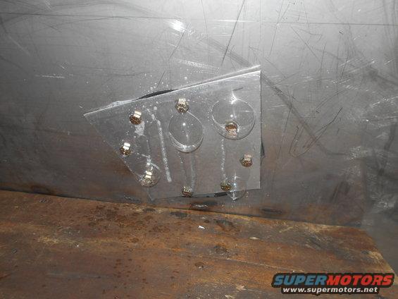
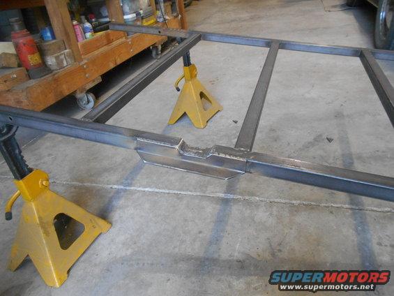
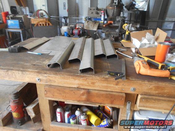
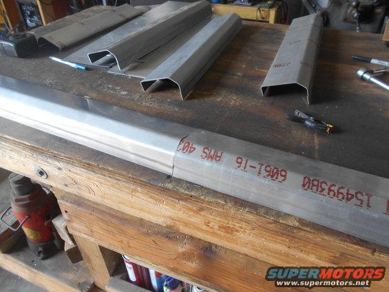
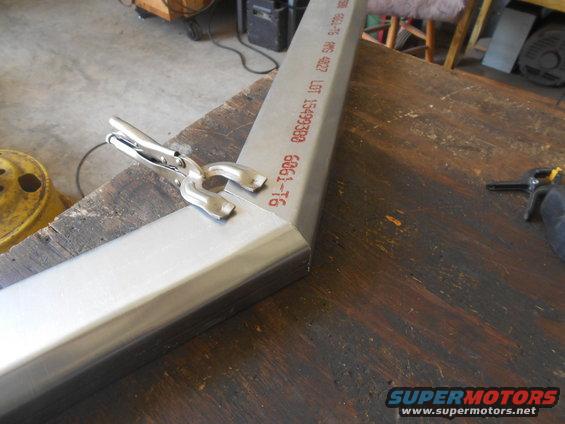
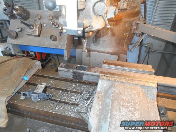
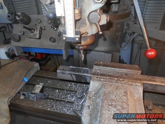
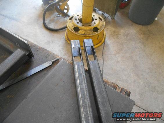
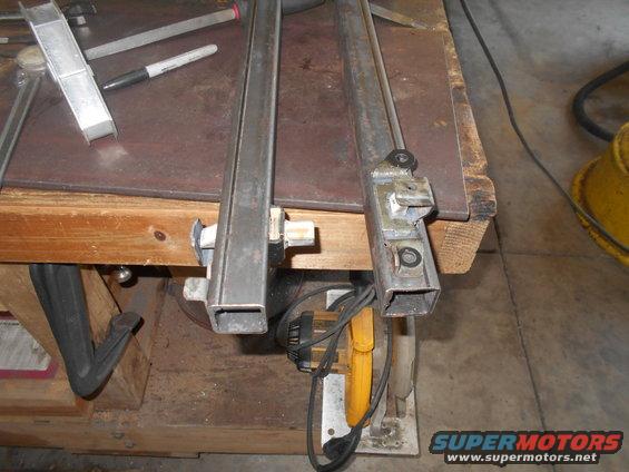
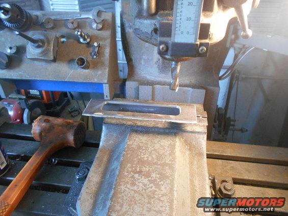
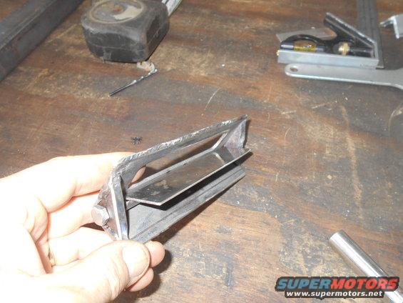
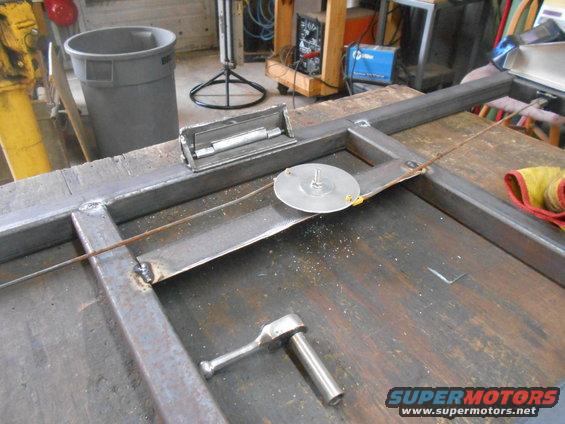
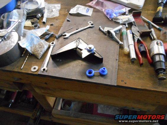
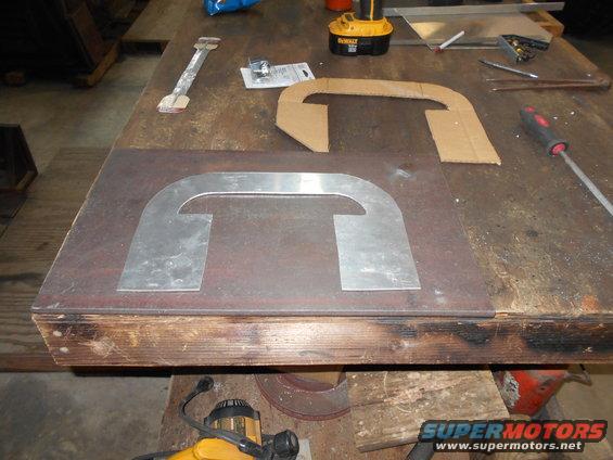
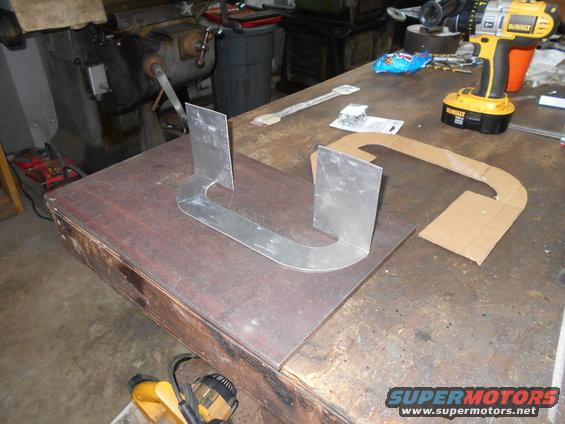
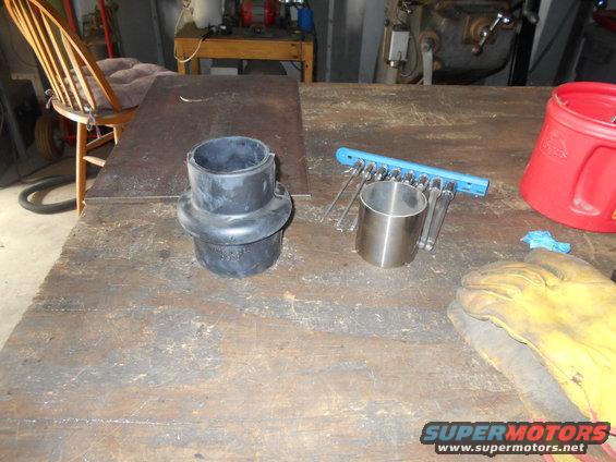
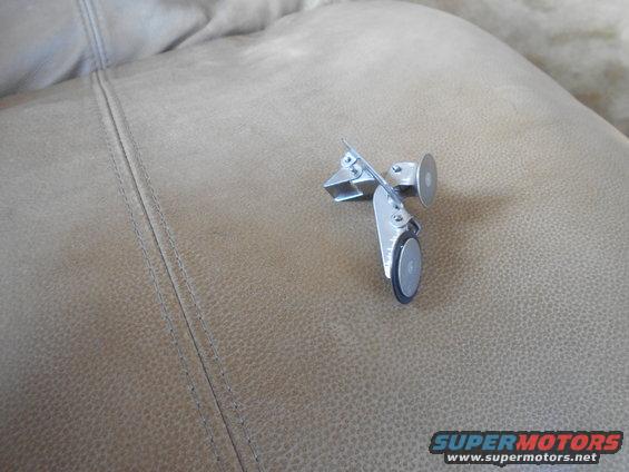
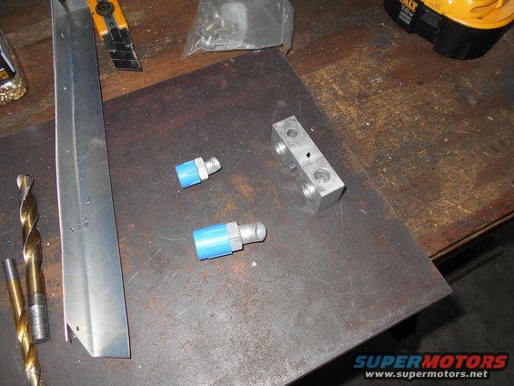
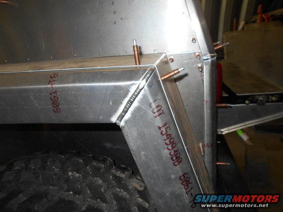
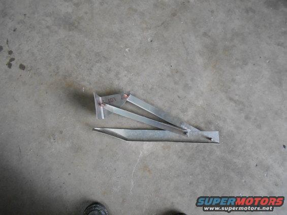
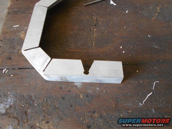
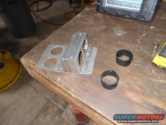
These are the pieces to be welded to make the bracket.
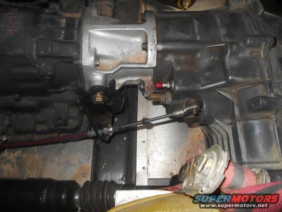
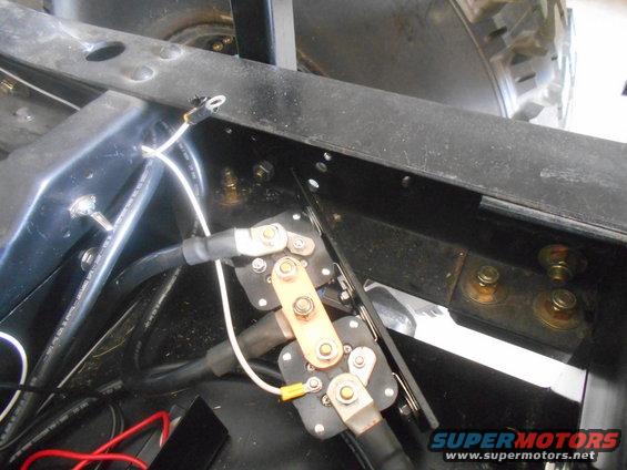
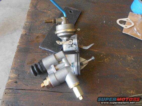
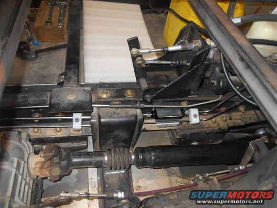
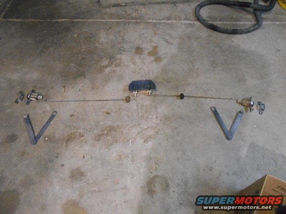
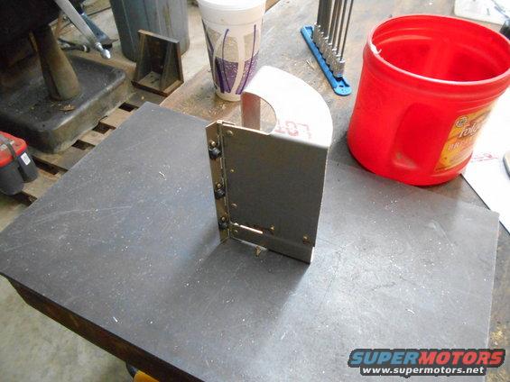
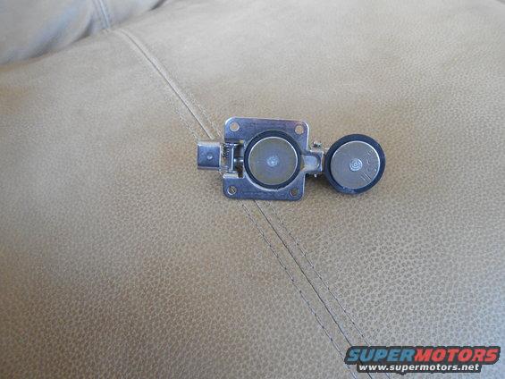
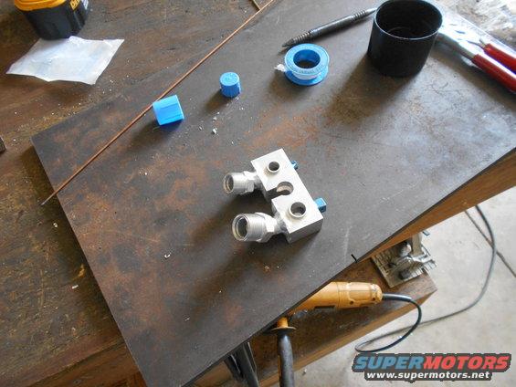
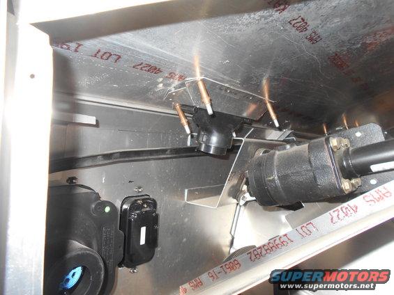
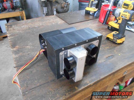
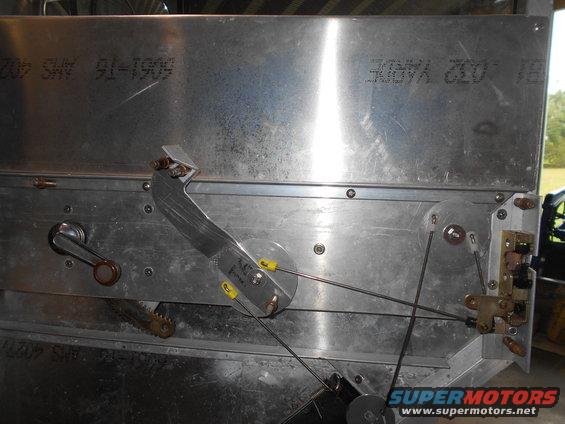
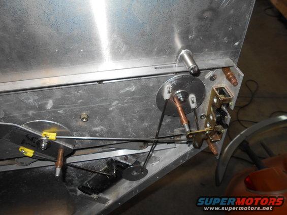
All welded, painted and bolted on. The swivel eye is held on the t-case arm with a c-clip.
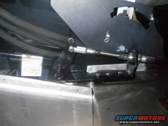
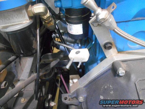
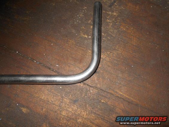
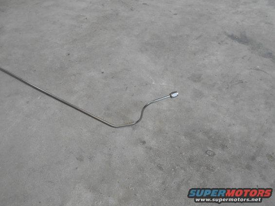
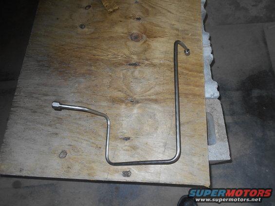
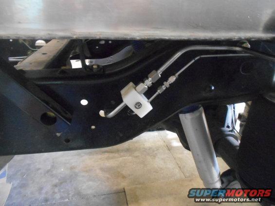
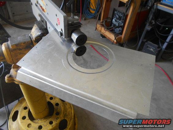
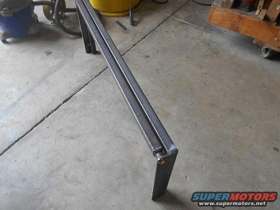
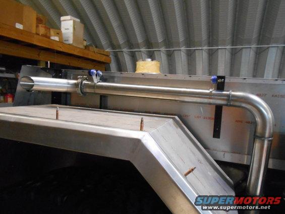
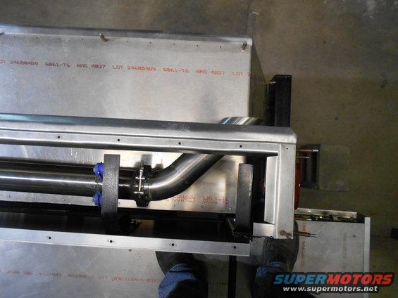
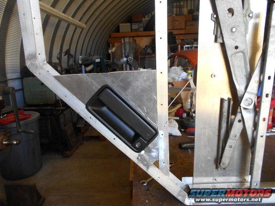
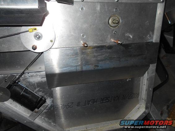
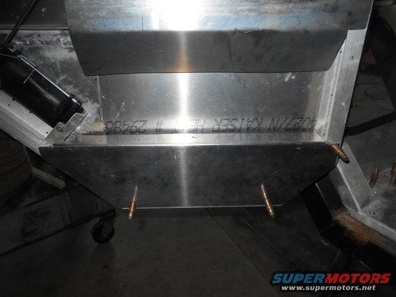
The front bracket was much more difficult to make, mainly because I had allready made the console. I had to hack this thing all up to fit it in the slim area I wanted to put it.
Eventually, I got it to fit.
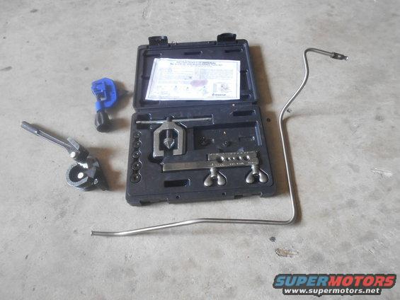
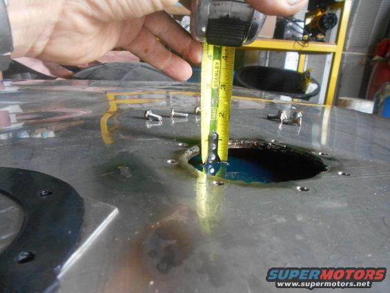
After I had it located, I had to measure to order the cable. I measure 8'. Since it doesn't matter if the cable is a little longer but can't be too short, I decided to get 8' 6" . So 8' 6" is 96" plus the 6". Of course 96 + 6 is 112", that's what I ordered. Seriously, that's what I ordered. Now a few inches long is not a problem, but 16" long doesn't. Nothing that another $100 won't fix.
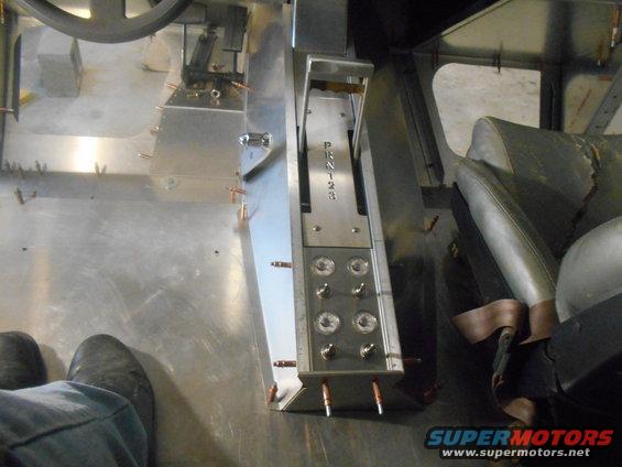
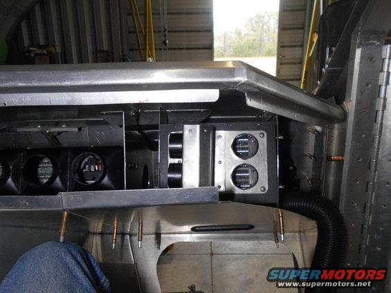
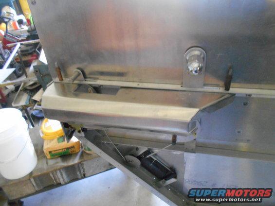
Anyways, the console cover fit over it nicely.
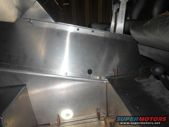
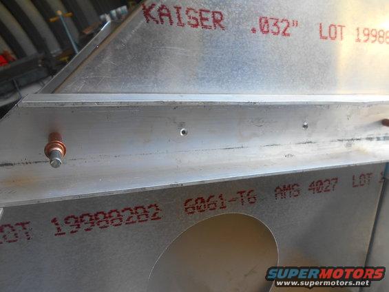
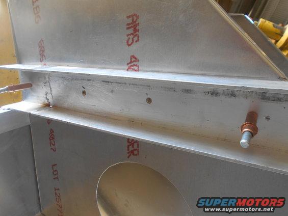
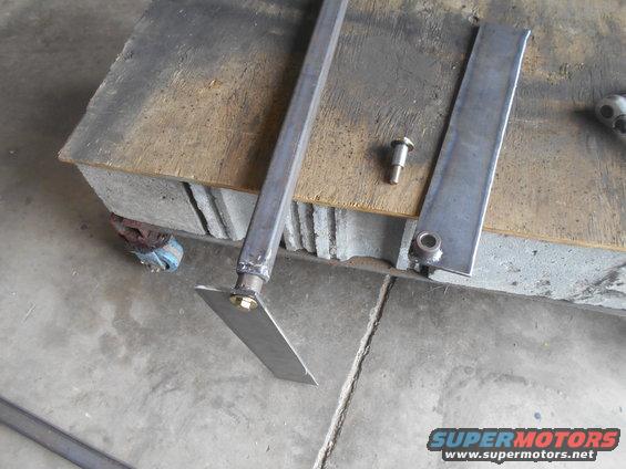
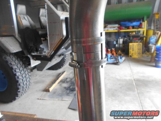
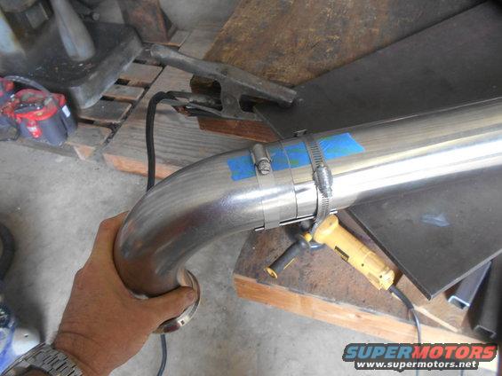
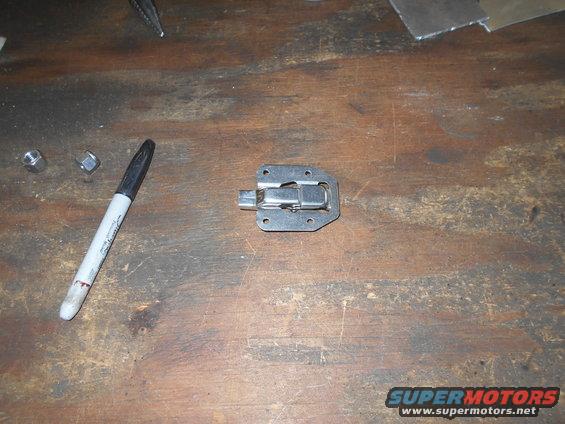
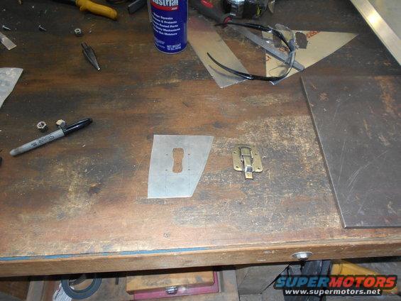
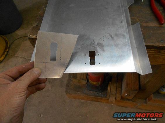
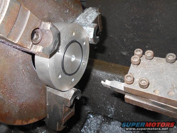
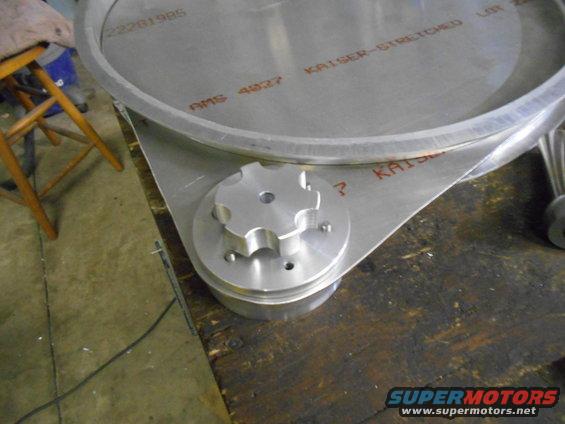
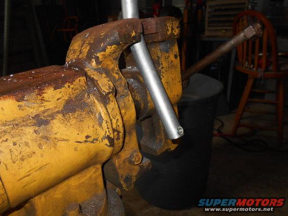
The hole is where shifter connects. The shifter is "keyed" by a slant cut on the tube.
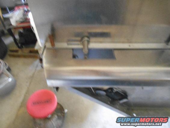
I attached a bent aluminum arm the the keyed tube.
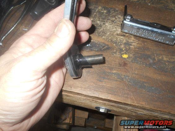
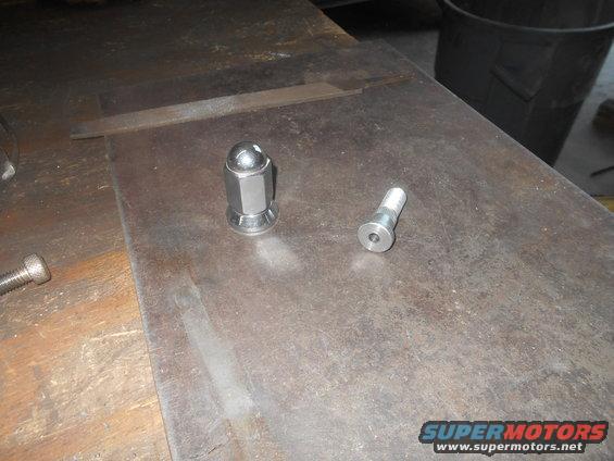
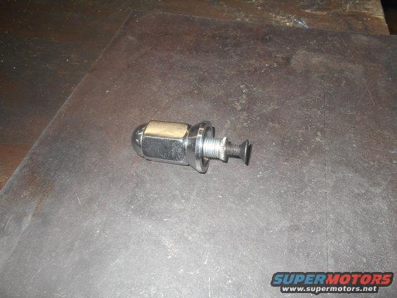
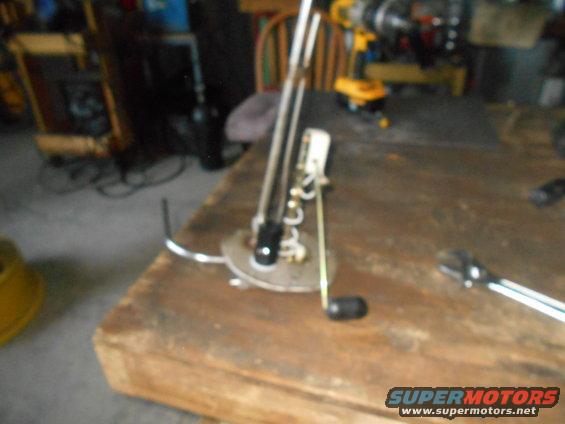
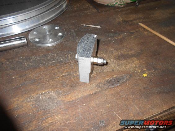
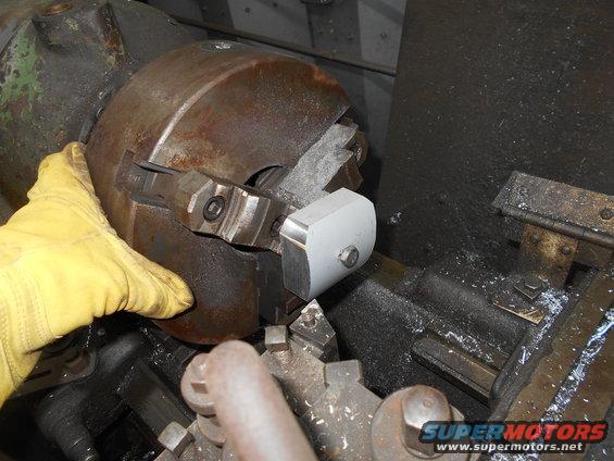
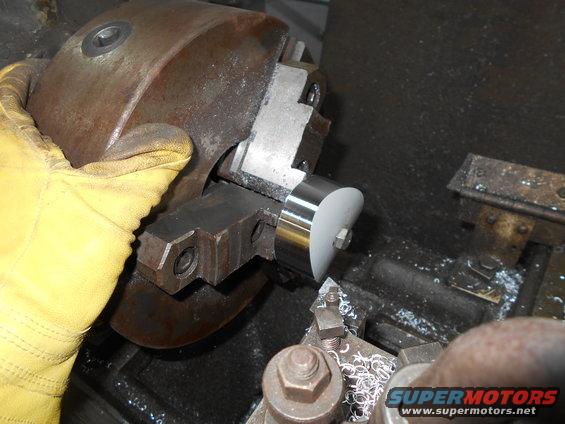
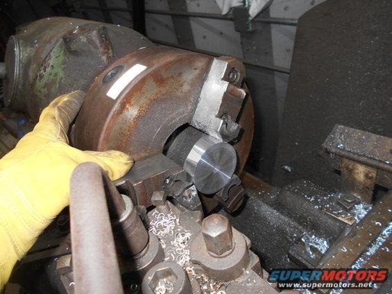
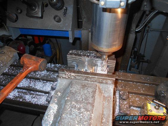
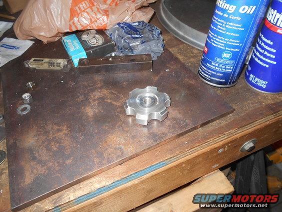
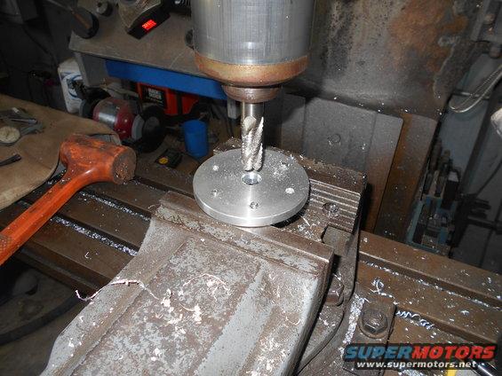
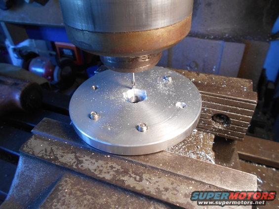
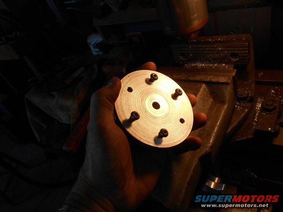
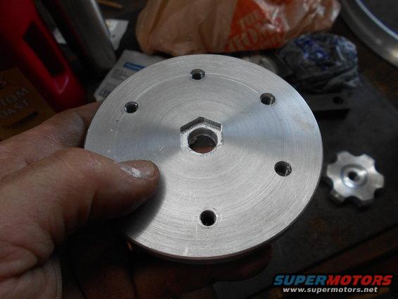
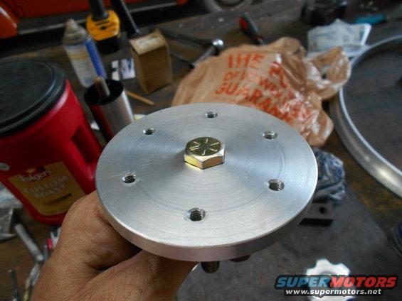
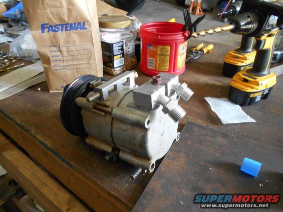
For the top of the shifter I got an idea to use a lug nut. I had a couple extra of the high quality nuts. This simple idea was kind of a pain to do. First I couldn't find a bolt with the threads to match the nut. Lowes and even Fastenal didn't have one. I ended up buying a lug stud. I didn't need it so long so I cut it and drilled/taped it for a small countersunk bolt.
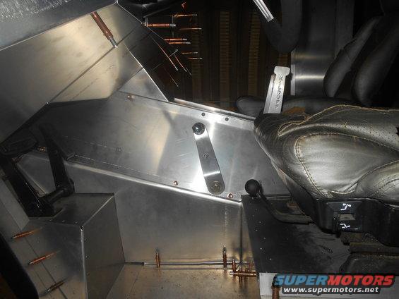
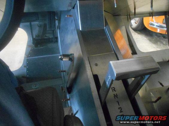
All finished, it came out nice. This is the whole way forward. (4-low)
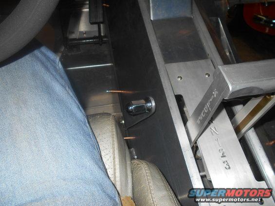
Here the shifter all the way back. (2-high) It's far enough over that it doesn't interfere with the seat or my leg.
Before I can work on this part I have to relocate the radiator. It will go in the side. Here you can see there should be room in there.
But I'm having fun with the console/dash right now. Here I made a little riser to get the shifter in place.
I had to make the driver's side of the console in two pieces.
Still needs lots of work, but I like it.
I got some progress to report on the dash. First, I made a glare shield.
I wanted this to shield the sun from reflecting off the lower windows. So I figured I should cut the lower windows.
I played with some cardboard to make a dash that wouldn't interfere with my line of sight to the lower windows.
Than I got to cutting metal.
Because the truck is so high, it's easy to see under the dash when standing outside. I couldn't leave the "underdash" open, so I made lower covers.
Continued
So after getting most of the dash clecoed together, it really got strong. It will even be stronger after finel riveting. I'm glad because you have a tendency to grab it when climbing in.
I might even put a pocket on the edge to hook your fingers in.
I like the way the glare shield looks from the front. I hope it can be seen after the windshield is in.
On another note, you might have noticed the angle aluminum on the pax side kick panel. I put this in to give some extra strength next to the glass. (The driver's side has the raised pedal section)
I was thinking I should make a foot pad so the pax has something to brace themselves in a exciting situation. Better than using the glass. LOL. Anyways took a day to make this.
It's going to be attached with a couple screws, but it actually fits so tight that I have to pound it on.
Update,
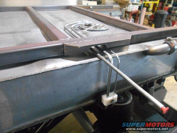
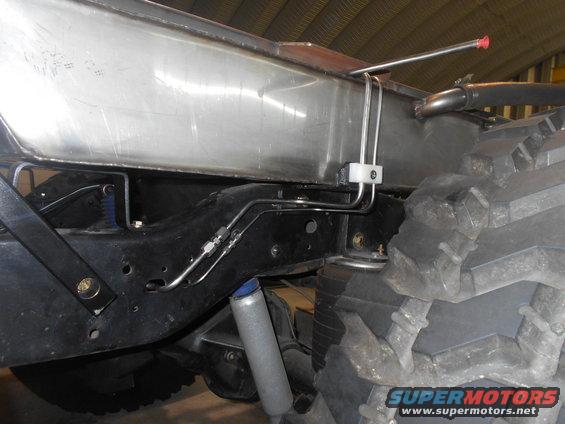
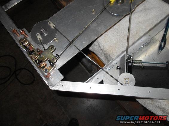
I never worked out a transfer case shifter, so time to through money and time at it. Since I had push-pull cables everything else, I went that route. I needed bracket on the t-case adapter to attach the cable sleeve. If you have followed this thread from the beginning, you know I swapped a aluminum adapter for a cast iron one. I like it, but for some reason they only put one threaded boss on the side for linkage to attach. (The aluminum one had two bosses) The problem with one is I had to make the bracket wrap around the casting so it won't be likely spin on the single bolt.
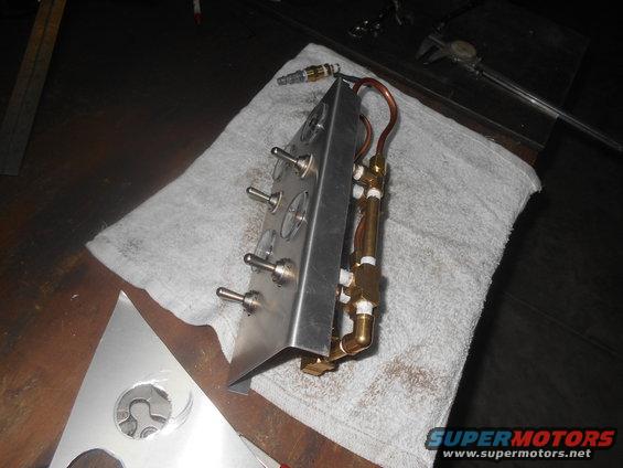
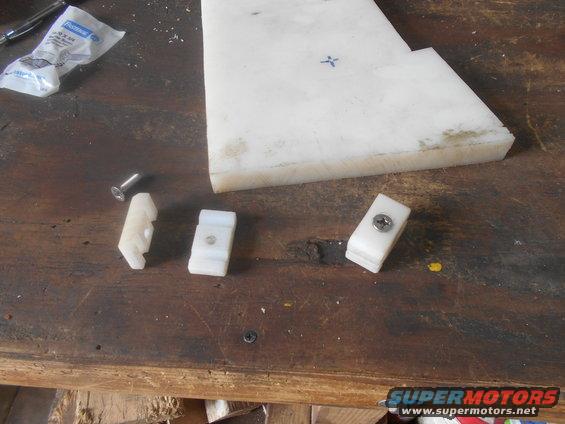
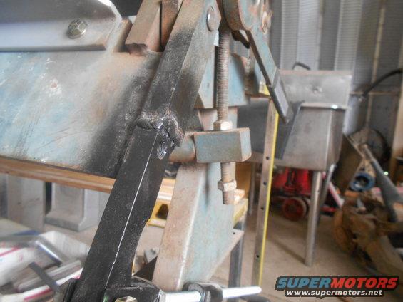
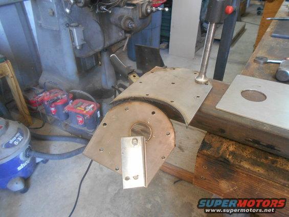
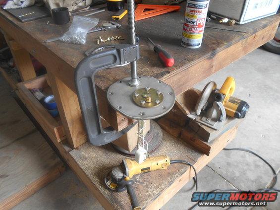
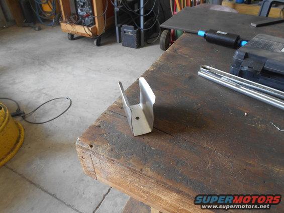
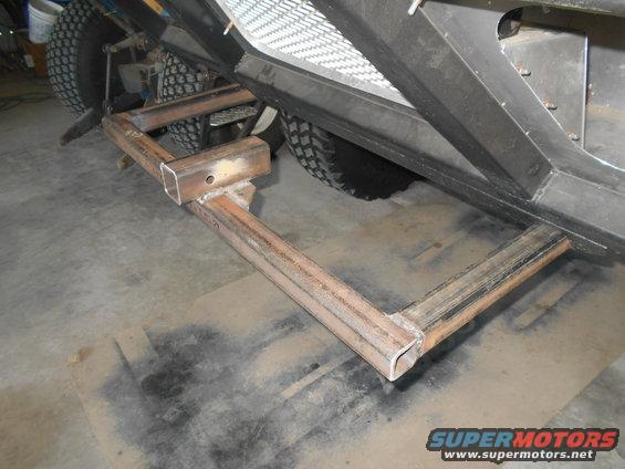
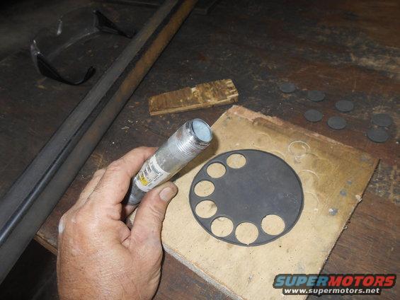
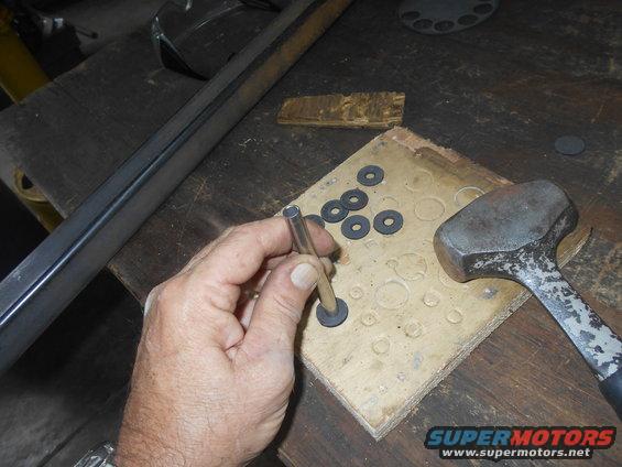
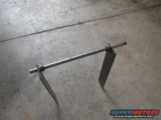
These are the pieces to be welded to make the bracket.
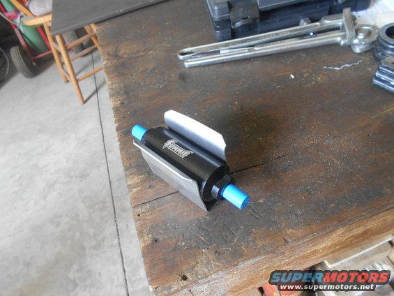
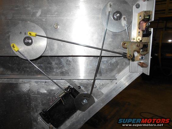
All welded, painted and bolted on. The swivel eye is held on the t-case arm with a c-clip.
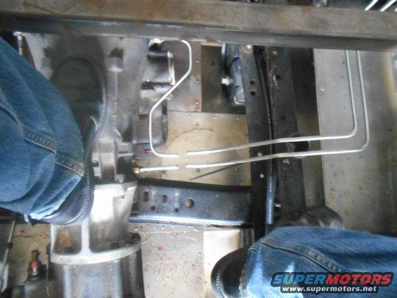
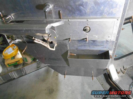
The front bracket was much more difficult to make, mainly because I had allready made the console. I had to hack this thing all up to fit it in the slim area I wanted to put it.
Eventually, I got it to fit.
After I had it located, I had to measure to order the cable. I measure 8'. Since it doesn't matter if the cable is a little longer but can't be too short, I decided to get 8' 6" . So 8' 6" is 96" plus the 6". Of course 96 + 6 is 112", that's what I ordered. Seriously, that's what I ordered. Now a few inches long is not a problem, but 16" long doesn't. Nothing that another $100 won't fix.
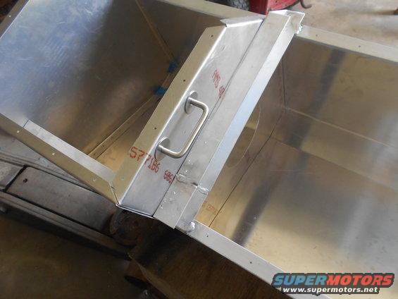
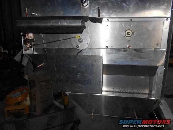
Anyways, the console cover fit over it nicely.
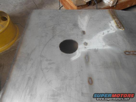
The hole is where shifter connects. The shifter is "keyed" by a slant cut on the tube.
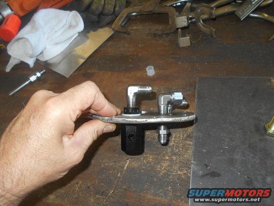
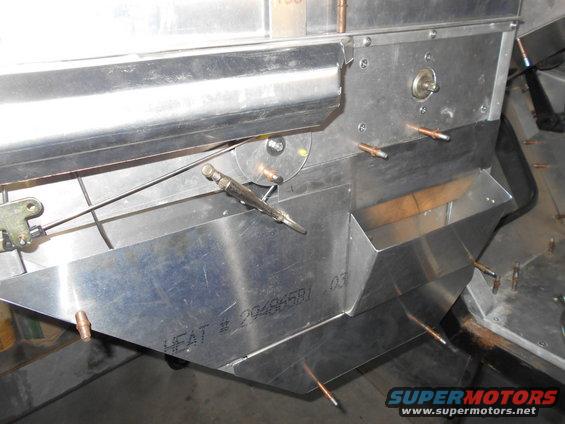
I attached a bent aluminum arm the the keyed tube.
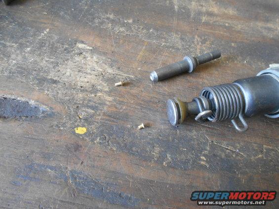
For the top of the shifter I got an idea to use a lug nut. I had a couple extra of the high quality nuts. This simple idea was kind of a pain to do. First I couldn't find a bolt with the threads to match the nut. Lowes and even Fastenal didn't have one. I ended up buying a lug stud. I didn't need it so long so I cut it and drilled/taped it for a small countersunk bolt.
All finished, it came out nice. This is the whole way forward. (4-low)
Here the shifter all the way back. (2-high) It's far enough over that it doesn't interfere with the seat or my leg.
Last edited:


 It looks awesome man, thanks for moving this over and I will continue to follow it. Carry on Brother!