What's new

1972 F-250 2wd to 4wd build

Working on front suspension improvements and modifications. Mainly bump stops v2.0.

v1.0 had stops under frame. To keep tire out of fender when flexed, they needed huge spacers and severely limit up travel.

v1.1 I moved them outwards as much as possible, where they can be higher up because Sine function. But coil over hit right side due to track bar movement and had to trim it heavily.

v2.0 is start over. Bump cans behind coil over, outboard of frame. Contact radius arm brackets.

But limit straps are there so step 1 was to move the straps in front of the coil overs. I made a set of tabs and tacked in left side. Right side had track bar bracket brace in the way, so cut that out. While fitting right side decided to change up mounting scheme from butt joint to a overlap which also gave a bit more room for fasteners.
cMT99IISaIKAav370H6Iy76WYi=w727-h969-no?authuser=0.jpg


Better weld, no grind. Also welded other side of inner tab. I decided to go double sheer as there is some side loading on left side due to track bar moving axle left at droop.
TwJfA03vv5eTeCtxKZuMdcV9_I=w727-h969-no?authuser=0.jpg


Located holes such that droop limit was same as before. Upper is just a simple hole through frame. Hit with paint, put on lift to measure and test.
wObSpkh5_3d-TKUx6NAZQclLRq=w727-h969-no?authuser=0.jpg
 
Next step was the bump stop striker pad for the top of the radius arms. The grease zerks were in the way, so pulled arms to weld hole shut and move to a different location. Could have built something right on the arm itself but it would impact bushings, so chose to mount pad to axle brackets. The addition of the pads hold the width of bracket fixed, so had to be careful to shim slightly over.

Used some 3x6 3/16 rectangular tube to utilize the radiused corners. Then attach with simple flat bar and overlap welds.
Used some washer with a flat cut to locate pad height and make sure socket still fits on fasteners.
8P5RY-0Ds3G2TzDHPp4NjzlyJ=w1292-h970-no?authuser=0.jpg


Then on to the upper bump can mounts. Spent a few hours making cardboard templates until I was happy and transferred to 3/16 plate. Used table to build the shape and test fit.
8WHTZjlQpdRD4UthLm0WaHxgm=w1292-h970-no?authuser=0.jpg


Axle moves forward and right as it goes up so have to account for this in placement. Can is angled out and back a bit to match the coil over and make everything more complicated. Have one side tacked in so will start on the other and see what has to be redone again.
Created a pinch point for the brake line so may have to redo all of that too.
iS9n4t4EkYAhLD8NZACYlKVU5=w1292-h970-no?authuser=0.jpg
 
After a 2nd look wasn't quite happy with placement of bump cans so popped them off. They were angled out to much, turn out the frame rails are angled in at top 2-3*, so the added 2.5* of brackets was too much. So disassembled them, cut the side pieces parallel to remove the angle, and rewelded. Also added a brace to the bottom only with an opening to allow rocks and water to exit.
ZrM0qilsv-qPpcvM8g_YBZ87In=w567-h756-no?authuser=0.jpg


Same for other side. Given the axle moves laterally with height change, the right side is out a bit farther. Put the bump tubes in the lathe and gave them a polish, then clear coat to make them look like fake air bumps, bro.
j3Axmd3G--5SbAHuNiuCqB2a4=w1008-h756-no?authuser=0.jpg


Going to try some new foam bumps after a look here:
-If you don’t have room for air bumps, foam urethane bumps stops are a great choice.
-Foam urethane isn’t tuneable like air bumps, but their progressive nature makes them more comfortable when frequently contacted near ride height. Foam urethane is also less durable.

They are much softer than the poly bumps I had, will see how they work. Same 3/8-16 mount so easy to swap.
Welded up the mounts, but used restraint. Did not weld can tube to bottom brace, and only welded 1" on each corner so I can cut can off and move if needed. I think 4" of linear weld is close to 1 sq in, so 60,000 tensile, which should be plenty. Then some paint inside and out before welding them on to the frame.
4mKSp8nZKYIfboK2q7-IN5O6j=w1008-h756-no?authuser=0.jpg


So tacked back on for further analysis paralysis. Final welded contact pads on radius arm brackets. trimmed weld to make sure 7/8 socket still fits.
Mz_oVU7m2KdlZiBwAGWpj6EnC4=w567-h756-no?authuser=0.jpg


So just final weld and test-n-tune left to go.
2utUk_m3ww-Ptrr1-aEazUpF0=w1008-h756-no?authuser=0.jpg
 
Finished welding the bump mounts to the frame so fab job is done and drove the truck today.
I welded about 2/3 of the seam length, with vertical up welds. They are ugly but hot and deep. :laughing:
I also added 1/2" of preload to coil overs (1/4" to 3/4") to raise ride height for more vertical up travel. So hope to get a total of 1" more bump gap with out-boarded mounts and ride change. 5"+ down and 3.5 up.
Need to test and tune bump height.

0nBHQwiPwQCMfG2sTwNb_qo__f=w727-h969-no?authuser=0.jpg


I did a full brake inspection, but now brakes are now pulling to left, so perhaps I overheated brake fluid welding so close to the mount and lines. Heated frame and whatnot. On left side I welded only half and waited for things to cool. Guess I'll bleed the right side and see what happens.
UIZ4TlAvRg8wV7Izzp8b9Nr8k=w1292-h970-no?authuser=0.jpg
 
Well fuck.
Had low fuel pressure problem on way home yesterday. Died at stoplight. Luckily I had recently labeled all the fuses and relays and had a jumper in the box. Jumped the pump but wouldn't get more than 20 psi, would fire but not run.

Grabbed a strap and got a tow out of intersection to nearest parking lot. Was fairly hot 110, so went to work diagnosing. Was happy to have an old towel to lay on and decent tools. Could hear and feel pump run. Nothing out of return line. Pinched off return hose, but wouldn't build pressure. Hmm. Cracked supply post filter and had some pressure, enough for a hot fuel shower. So regulator is doing what it should, but not enough pump pressure/flow to regulate above 20. Also won't hold prime. Thinking either leak in fuel line between pump and fuel hat/sender unit or faulty pump. Next step is to drop tank, so hopeless and called for tow truck.

So that is 0 tows in first 30 years of driving and 3 so far this year (other 2 for my Cobra mustang)

So this is the one case where a toilet (aka carburetor) would be helpful. The only one so won't even consider.

But last time I drove it was 100 mile trip out in desert, without another vehicle along, and did not see anything but SxS out on trail. So could have been worse.
 
Popped the bed off to access fuel tank pickup. I think it was faster and easier than dropping the tank. 6 nuts, one plug and filler. Oh, and a shop with a lift and A/C :)
W4AsawYJbEP2x2VjlY6cnrhQ4B=w974-h731-no?authuser=0.jpg


Pulled pickup and found split hose. Trying to fully understand what happened. I used hose and clamps that came with the pump. I get that worm clamps can cut the hose and help cause a tear. It appears that the pressure pushed on the pump and made it sit crooked in the pickup, making the otherwise straight hose a zig-zag and hence the failure at bend. So need to figure out how to make sure this doesn't happen again. Maybe secure pump body to return line or a metal tube to keep hose straight. different hose, smooth clamps.
juFEauqSbO-9DHLtR5eohjrlo9=w727-h969-no?authuser=0.jpg
 
I would try to grab some OEM fuel hose from Toyota or Honda and try that. I haven’t had the best luck with parts store brand
 
I've always had great luck using the hose that comes packaged with the replacement fuel pump.
 
Hose clamp around the pump to the the tube there should be plenty to prevent that misalignment happening again. Make sure the replacement hose is meant to be submerged, for whatever reason that makes a difference. I'd assume the stuff that came with an in tank pump would be rated for that use.
 
I might have missed it, but is there anything retaining the bump stop from sliding up? Those pinch bolts aren't really meant to keep them from sliding, they need a step at the bottom.
 
Thanks guys.
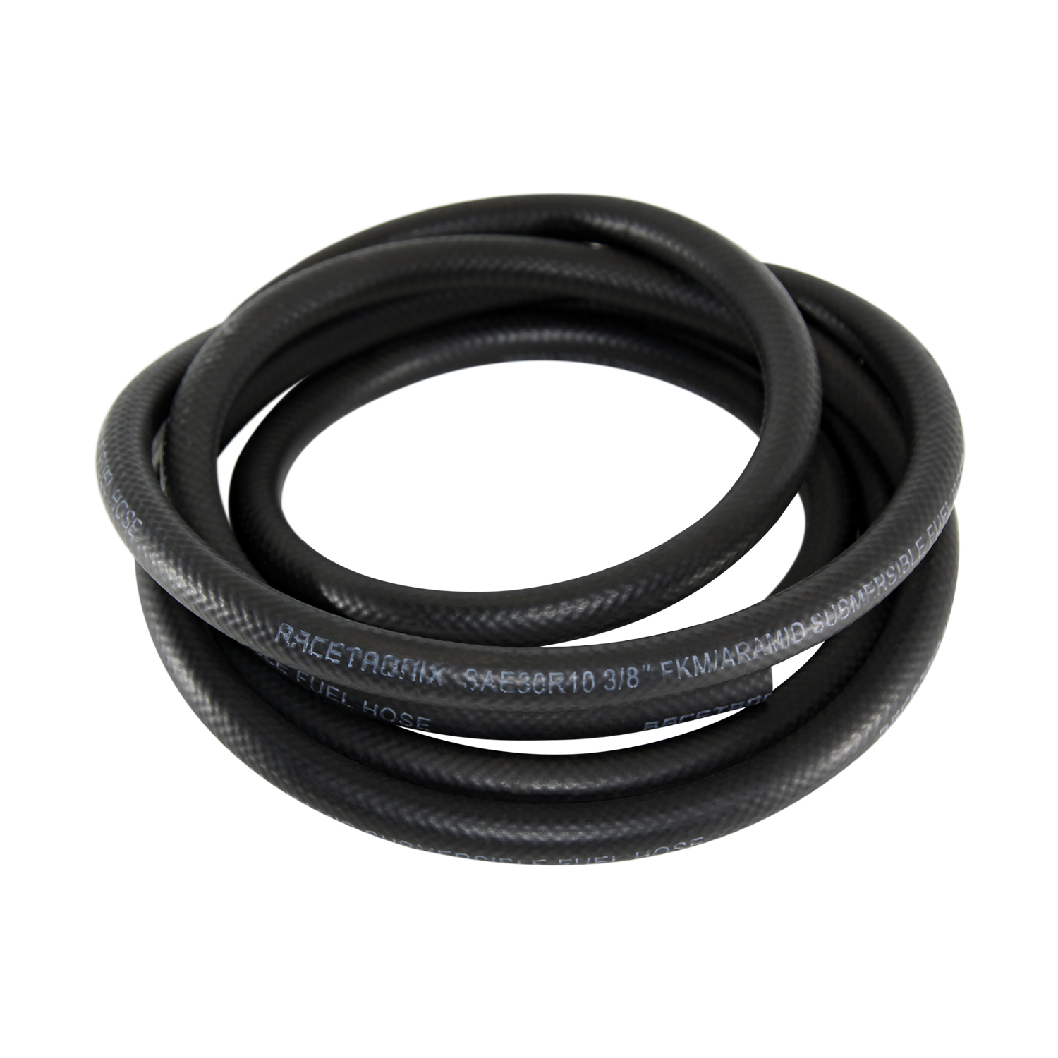
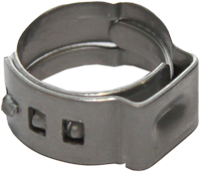
I found some SAE 30R10 submersible fuel line. 3/8" is sold out almost everywhere, although I found a source (tanks Inc above appears to have it too). Going to use smooth no overlap Oetiker clamps in specific sizes. Also bought a cheap assortment with a crimp tool.


I had another piece of 'unmarked' tubing from tank pickup assembly. It is 5/16, and is too small to fit the 340 lph pump. The existing failed hose appears to be 5/16, so maybe forcing it on the 3/8-ish barb made it fail.

The metal supply tube in the pickup/sender necks down to 5/16-ish at end, so I think it was designed for a 5/16 outlet pump. Contemplating cutting off that section, adding a nipple, to keep it all 3/8 on supply side

I slapped it back together with some 3/8 J1532 TOC hose so I can move the truck around. Tested depth, goes in smooth doesn't bind on tank floor. Regulates at 60 psi now.
 

Attachments

  • Oetiker.jpg
    Oetiker.jpg
    7 KB · Views: 7
I might have missed it, but is there anything retaining the bump stop from sliding up? Those pinch bolts aren't really meant to keep them from sliding, they need a step at the bottom.
No, I figured the pinch was supposed to be enough, and be adjustable.

Weld a ring on at the desired height or at bottom and use spacers I guess.

Thanks for commenting and helping the Newb.
:homer:
 
Started on Exhaust 2.0. Pulled tail pipe and hacked off muffler. Mocked up mufflers, they are wide and don't leave much room between driveshaft and frame. Will need to rework hangers and collector extensions. Long way to go....

New setup will have more case volume and only 4 cylinders going though one muffler instead of 8 through two.
iExkYMwS6rH1kCcCp-bt4CSlZ=w1216-h912-no?authuser=0.jpg
 
#10 N2O bottle is same size as CO2 so bottle mount is already done.
Going to finish fuel and exhaust to get truck back together before fucking around with nitrous system.

Umpr53eXUMXlp-YxkU_jVz467=w1292-h970-no?authuser=0.jpg
 
Wrapped up the fuel system repairs. The TOC hose was already a soft slippery noodle after a week of soaking in fuel.
Installed the 30R10 hose and Oetiker clamps. The larger size 16.1mm clamps I ordered were just right to get 3/8"-15.8 mm hose over the barbs.
The metal pickup supply tube necks down to 5/16, I left it intact but put the clamp up on the portion that is still 3/8. I don't think the Oetiker style would crimp down enough to work on 5/16. Also the hose would be over compressed. I also put a worm clamp around the pump body and return tube to hold it in position.
UCWZvRSItwcEQQscczMPCK_YF=w1292-h970-no?authuser=0.jpg
 
Making progress on exhaust v2.0, if feature creep counts. Decided to rework the left collector extension, is it was tight to trans cross member due to engine being moved down and back for A/C. Time was now as other end was getting connected to new mufflers.
Did simple partial cut to shape pipe as to gain clearance.
LYQglk-exGM7frZPPN9bs3xia=w1292-h970-no?authuser=0.jpg


Like it never happened
K_NuQyJASe4BgT2gjgbj1Mo5l=w1292-h970-no?authuser=0.jpg


Got creative with clamps, straps and bars to position mufflers in chassis. Space is tight between driveshaft and frame. Once located fit existing tubing from mufflers to v bands.
IFIzXHvVxTNN4xU50tpPljDJA=w1292-h970-no?authuser=0.jpg


Moved hanger to back side of mufflers and used it to space and connect the two cases together. Not ideal location but fit well with offset outlet. Tailpipes can be removed and rest of system is still supported.
FNfKGKY25v8_G4FfRCHzZjSKc=w1292-h970-no?authuser=0.jpg


Also added a cross over tube, h pipe, equalizer, whatever.
COzWYnXIRJVDBMk_O2Ua1-aWK=w1292-h970-no?authuser=0.jpg
 
Tail pipes in. Used SS tube and bends. 308 wire on C25.
BK3Mkdae7wNgbvzYtBIkb0R1G=w1052-h789-no?authuser=0.jpg


Reworked the existing hanger mounts to keep the 'V' shape to limit sideways wobble.
rqZTg8p1n4uEAI1CUjHFhjqOv=w1052-h789-no?authuser=0.jpg


DFX4m-urIU6GEbDaeCLsSHFnQ=w1052-h789-no?authuser=0.jpg


Not totally happy with how pipes lay going to turd polish at later time. good enough for test drive.
IKS3TNzTE0-V39Ce2Oi5uhfgt=w1052-h789-no?authuser=0.jpg
 
I 'fixed' the upper tailpipe so they lay nicely together. Cut pie slice and rewelded. Went a bit over on angle and tips stay together without a fastener or weld.
z_R47E0bGhARWDfAL_C_fzXPY=w1216-h912-no?authuser=0.jpg


Much better. Still too short, but can address that later. Extend, cut to same length, custom oval tip, or something else.
2f76Jry3TpLc5GZ_jrBizgizO=w1216-h912-no?authuser=0.jpg
 
Made some stop rings for the bump stop tubes. Didn't have any 2" ID tubing, closest was 2" sch 40 pipe. Trued up ends in lathe and made a pretty looking ring. Cut a slice out to reduce ID for a slip fit, rewelded.
HI81LMa1zpcLOWHI3WOwOQOjk=w1216-h912-no?authuser=0.jpg


To secure I put a decently hot tack each 90*. Weld in in compression so I think it will hold under most extreme conditions. Can easily cut and move to adjust. I moved the bump down 1/2" based on previous test and the fact that foam bumpers will compress more than the poly ones. Will see how they work.

I gained 1/2" of bump gap by outboarding and 1/2" by ride height increase. Then -1/2" for soft stops. This still yields only 2.5" of gap with the foam setup. Need some more miles to see how it handles bottoming out at speed.
fuXU3tu8E7Ty6Q6riUObPGDtwX=w684-h912-no?authuser=0.jpg
 
Thank man.

New exhaust system is quite different than before.
Quick recap, OG system was just the 2-into-1 muff and was blatty at WOT. dumped behind axle.
Added 2nd 3" muffler in tail pipe, was to quiet at heavy throttle. tailpipe out the back

New 2.5 dual system is louder at all times. Idle is mean and nasty. Sounds like the big block with cam it is.
Tip in and light sounds mean and clean.
At 30-50% throttle there is some drone/resonance at any RPM. This is unfortunate. Still sounds burley. Lots of exhaust gas flowing.
Heavy throttle and WOT have a nice tone. I like it. no rasp/blattyness.

So I like all of it better except the drone. The existing system wasn't that quite on highway either. Such is life with a big old truck. Cab has a ton of sound deadening and cracking the door or window is a reminder of what happening underneath.

Going to leave as is and move on to other things.
:beer:
 
Next step is to un-fuck the steering with a high steer arm on passenger side. The steep angle of the drag link rotates the tie rod as you turn the wheel. It drives fine but makes odd noises as you change direction and TR twists. Was never happy with it. Pitman arm end is maxed out on angle and limit straps are set to protect. Might get another inch of down travel with moving knuckle end up. Other upside is flatter drag link, that allows flatter track bar, less lateral movement/bumpsteer.

So ordered parts from Sky offroad and going to send my P knuckle to them to get machined for the arm. Have to redo the linkage bars and whatnot.

While truck is apart can install nirtous system. Looking forward to the custom install.
:smokin:
 
72 ford has had intermittent hanging idle issues. Sometimes have to blip throttle to get it to idle down all the way. Found similar issues on Holley support forums and seems solution is to re-center the secondary throttle plates and add a winding to the secondary return spring. I confirmed issue by bumping only secondary throttle blade shut with screw driver and observing drop in RPM.


Pulled throttle body to access captive screws on bottom of unit. backed off idle screw to get full closure and carefully centered them in bores. Noticeably less sticky. Adding turn to spring was a bitch but got it done.

QXutMYirKQRH9BlBT1lUOBHGaa=w567-h756-no?authuser=0.jpg


Contemplating manifold setup of spacers with addition of nitrous plate. The existing Jomar power cone spacer has a clover leaf shape that allow the 2 planes of intake to share air adding ~15 hp on dyno at high RPM for this combo. Unlike a toilet/carburetor the EFI unit already has an open area for IAB that allows leakage. The nitrous plate is an open plenum design with spray bar in same direction as plenum divider, so it also allows some leakage but not too much. So plan to abandon the power cone and run only the nitrous plate as it provides the same effect.

Coo94YZwM3oV4AUcsohRW-VY_=w1008-h756-no?authuser=0.jpg


With TB off did some mock up of solenoids and plumbing. Going to put everything on right side away from linkage and crap on left. FPR is on right side so have to space out to clear.

_n3M48-p9rcQzZgj08f1mx_je=w1008-h756-no?authuser=0.jpg


WPX_hvJn885eo1Wrow5Hy2HBe=w1008-h756-no?authuser=0.jpg
 
Top Back Refresh