What's new

Project Iron III Oxide: A Snowball Effect

D_JEEPER

Picked the wrong week to quit sniffing glue
Joined
May 21, 2020
Member Number
870
Messages
738
Warning... this is a recap thread to this forum.... being revived after 2 years of no progress!


Back story. Back in 2015, I noticed some rust in the typical spot in the TJ frame at the rear lower control arms. My original plan was to cut the cancerous section out and replace it with one of the online kits you can purchase that scabs over and welds to the good part of the upper frame. After some thought and finding out that the rust extended beyond where the scabs would cover, I decided that a back-half-replacement was in order. I would literally be replacing half of the frame.
20160326_144229.jpg
wAAACH5BAEKAAAALAAAAAABAAEAAAICRAEAOw==
20160306_153148.jpg
wAAACH5BAEKAAAALAAAAAABAAEAAAICRAEAOw==
20160326_183118.jpg
20160326_183059.jpg

My extensive search yielded overpriced frames for upwards of 1500-2000 bux...and were of a different year than my 97 with the 4.0 instead of the 2.5, so it would require motor mounts and transmission skid replacement. Too much work. I was able to find a smashed 2002 frame for $200 that took a significant hit in the front, but the rear 70% was salvageable.


I decided that since I was going to replace the rear of the frame, I needed to do it right. Sleeving, plug welds and stairstep cut seemed to be the best way...maybe even overkill. I also decided to purchase a RockKrawler long arm upgrade. Since I was doing so much work, might as well toss in a 5" stretch.


I stumbled upon a set of axles from a 1979 F250... HP HD44 front and D60 rear. The previous owner was doing a full restoration and had these sandblasted, ball joints replaced and brakes/bearings redone. He needed them gone ASAP to make room for a new chassis so I scored them for $350. GAME CHANGER.


Now I am doing a full width stretch long arm build
evil.gif


On to the dirty work... Step one was to fix the very cancerous frame. I started beating the frame with a welding hammer to see just how far I had to go. I decided to stair step right at the center body mount because I could use the mount itself to position the donor section onto the original section. To sleeve the frame, I cut two identical sections of frame, then cut those down and rewelded them to sleeve inside of the frame. They didnt have to be pretty, just something to plug weld and weld the seam of the stairstep cut.
20160326_162445.jpg
20160312_210624.jpg
20160326_162455.jpg
20160403_172148.jpg
20160313_154256.jpg
20160326_174642.jpg


Some initial fitting. This part was a ginormous pain in the ass because of the shape of the frame. You cannot just SLIDE the frame section in because at this part, the frame is angled inward. You have to shimmy the donor frame above the old frame and drop it in place. With my limited available tools, I was shoving wedges of wood between the rockers and old frame in order to drop it down low enough.


I wanted this to be fairly unnoticeable unless you knew to look for it.
20161002_153213.jpg
20160824_193822.jpg


I ended up being within 1/16" of perfect (length and diagonals) Since my control arms will no longer be centered off of the stock control arm brackets, this was exceedingly sufficient.


At this point, I was building a house and this project was sidelined for a few months (like...7
rolleyes.gif
). I have recently picked back up on it. With the new house...came a new garage....with 3 bay shop and a lift
smokin.gif


Originally I was going to build some fish plates to reinforce the splice zone, but since I was going to do the Rock Krawler long arm upgrade, The 3/8" steel brackets would be welded in as a C channel exactly around where I had cut. Double win! This section of the frame is arguably stronger than ever so I have no SERIOUS concerns about it breaking.


Note: Judge not my welds, for these are flux core from my Hobart Handler 140 (Cranked to max for this...)


Later, I switch to a borrowed Hobart 230 with .035 and 25/75 gas.

20170701_183713.jpg
20170709_161803.jpg
20170701_192648.jpg


Nice beefy flat belly skid. Also good to know my motor still has enough motor oil in it to leak :rolleyes:
20170709_191532.jpg
20170709_175239.jpg
20170709_191343.jpg
 
I found a set of H2 rims to run locally. Originally I was going to run some 12 bolt H1 beadlocks, but I am keeping my 4 banger so reducing rotational mass is a plus. I will just be mindful of how low I drop the tire pressure while offroad
. Click image for larger version Name:	20170711_224436.jpg Views:	0 Size:	159.7 KB ID:	323860
This is how I move it around the shop when I need to use the lift for other vehicular maint. Ghetto fabulous

Click image for larger version Name:	20170805_150751.jpg Views:	0 Size:	137.3 KB ID:	323861
Now on to the Axles and stupid heavy shit.


First of all, my little hobart handler 140 has been amazing up until now. No way would I EVER consider axle bracketry or suspension work with a 110v welder. So I reached out to a buddy of mine and he graciously let me borrow his Hobart 230. Plenty of heat for axles :). I happily fronted the consumables (gas, wire, tips). I also had to drop in a dedicated 50A 220V circuit from the panel. I chose 6ga wire since it was only about 15 feet.
Click image for larger version Name:	20180307_204548.jpg Views:	0 Size:	224.0 KB ID:	323862

So as far as the axles go, I settled on a TNT truss for the front. I really liked their modular built-to-order system. They even had a specific option for the Rock Krawler long arm suspension. I ordered their truss with front stretch coil buckets in case I wanted to stretch in the future, drivers side upper control arm bracket, shock mounts, raised track bar bracket, and high clearance (or low profile) control arm mounts.


I will admit, this is the first time I have EVER done axle work, so LOTS of research took place between the last picture and the next, thus a time lag.
Click image for larger version Name:	20180331_165832.jpg Views:	0 Size:	185.5 KB ID:	323866 Click image for larger version Name:	20180331_165832.jpg Views:	0 Size:	185.5 KB ID:	323866 Click image for larger version Name:	20180331_165832.jpg Views:	0 Size:	185.5 KB ID:	323866 Click image for larger version Name:	20180331_165832.jpg Views:	0 Size:	185.5 KB ID:	323866
Ok, stop. Can we just take a moment to absorb the 12 passes of booger weld for a 3/8" plate on the axle? This shotty welding took about 2 days of grinding to clean up. Luckily for me, it looks like it was a low-amp cold weld all the way so I am not too concerned with axle housing warpage. Dat porosity tho. :shaking:
Big ol :flipoff: to the creator of this shity bracket.


*deep breath*
Ok, let's continue.

Click image for larger version Name:	20180414_155718.jpg Views:	0 Size:	198.6 KB ID:	323871 Click image for larger version Name:	20180414_155718.jpg Views:	0 Size:	198.6 KB ID:	323871 Click image for larger version Name:	20180414_155718.jpg Views:	0 Size:	198.6 KB ID:	323871 Click image for larger version Name:	20180414_155718.jpg Views:	0 Size:	198.6 KB ID:	323871

I began prep work on the frame of the jeep to remove all of the old control arm brackets that were in the way/ no longer needed. The upper front control arm brackets are integrated into the motor mounts so I left them for now. If they become a clearance issue in the future, I will remove or trim them back at that time.
Click image for larger version Name:	20180417_184458.jpg Views:	0 Size:	157.9 KB ID:	323872 Click image for larger version Name:	20180420_205126.jpg Views:	0 Size:	208.8 KB ID:	323874

Here is where you REALLY take your time, measure 50x and then 20 more. I am sure a good majority of you can do this in your sleep but, being a noob, I wanted to make sure I did this right.
I set the jeep at appx. ride height and began to check my angles. I read that you wanted somewhere around 6 degrees of positive caster, so that was my axle preset. From there I wanted to see where the axle would be positioned under the jeep with regards to the stock coil buckets. I noted that to I needed to rotate the truss backwards a few degrees to prevent the dreaded coil spring bow. (I am not doing coilovers YET....budget concerns and death threats from the wife haha)
Click image for larger version Name:	20180420_205126.jpg Views:	0 Size:	208.8 KB ID:	323874
I did a quick measurement of the wheelbase after the stretch and assumed ride height
Click image for larger version Name:	20180422_180428.jpg Views:	0 Size:	171.4 KB ID:	323875
 
Once again, having never welded an axle before, I decided to weld some metal similar thickness like the truss, then attempt a destructive test. if it held, I would proceed. If not, more practice. Since we have an endless supply of horseshoes that are anywhere from 3/8 to 1/2" thick, I grabbed an old pair and put down a quick bead. (Didnt clean it...sorry:flipoff2:). I abused it for about 10 minutes before calling it sufficient. Hell, if jeep and push out welds on vehicles like the ones I ground off...these should hold just OK :grinpimp:.

received_10108180055775132.jpg
received_10108179975530942.jpg
20180428_211020.jpg
20180428_212612.jpg

After some initial prep, I began my burns.
I read that patience is the key when welding an axle, so I welded it up in about 15 sections. I always checked that I could put my hand on the last welded area so that it was "cool" enough to weld the next.
received_10108182044190332.jpg
received_10108182224788412.jpg

They are not perfect welds by any means, but I think they will hold ok
received_10108182564886852.jpg


The pig, mostly welded up.
received_10108182561239162.jpg
 
Cant seem to figure out what is going on with my caster angle though.:grinpimp::laughing:
received_10108182878453462.jpg


So the install with the truss was a success.


I hooked up the long arms and ran a tape measure over everything. The angle finder showed about 6.5 degrees of caster with the front driveshaft a beautiful 2 degrees off from inline. :grinpimp::flipoff2: It has hubs anyways, so not concerned about highway vibes...but happy with that angle. High pinion for the win.
20180429_180631.jpg

20180429_175417.jpg


With visions of the axle brackets snapping off and rolling out from under the jeep, I am always anxious about structural welds....especially when the axle tubes are 1/2" thick.


I am happy with the angle that the coils are sitting. Notice, this is with the front unsupported by the lift. Seems it took my 3.5" RE coils and made it more of a 5"+ lift. I will need the clearance for the 38s anyways.

So that is where I am as of right now. I am about to do some work on the rear axle next. LUCKILY, the rear has exactly zero bubbafuck bracketry going on, so it will be much easier to do. I have my coil brackets, Rock Krawler triangulated uppers truss bracket, shock mounts and frenched shock mount on the frame to install yet. I will also have to weld in a new upper coil bucket to accommodate the stretch.

Plans for the axles are Detroit lockers (maybe ARB if I can sweet talk the wife), 5.39 gears (4banger love), warn hubs in the front, some sort of beefy diff cover. The gas tank will be the Genright stretch tank for up to 6" stretch with a D60. I will need driveshafts, brake lines, and other assorted nickel and dime stuffs. I will also be purchasing some sort of rear corner armor for the stretch and front tube fenders.
laughing.gif
 
The Rear axle is a Ford D60 Full Float, 30 spline...nothing fancy. For my 4 banger, that will be more than enough and I will REALLY have to try to break it.

First step was figuring out the driveline angle, or thereabouts. Luckily, RockKrawler made it really easy with a template piece of metal that gauges off of your stock diff cover.
20180519_155648.jpg

After setting up the truss, I checked angles, ran string, measured everything 15 more times, and finally burned it in. The truss came with an internal finishing/gusset bracket. I had to work pretty hard on that to get a good fit, but it turned out nice. I decided, for aesthetics/strength (mostly aesthetics, honestly), to run a full length bead rather than stitch it in.. I'm pretty sure my welding glove was on fire for most of this.

received_10108253631653482.jpg


Next challenge was a bit more tricky... locating the lower control arm brackets. Lots of math and calculated guess work went into this part. I wanted to make sure the control arm mounts were as high up as possible, without causing binding under articulation. I ended up with about 30 degrees down slope on the brackets. After welding those in, both outside and inside of the bracket, I bolted everything up to test fit.
received_10108256715633162.jpg
20180519_211004.jpg
20180519_200636.jpg


I had to cut off the upper coil buckets and track bar mount (upper triangulated rear control arms remove the need for it).
20180520_182918.jpg

Next step will be installing the upper coil mounts, axle coil mounts, outboard shock kit and axle shock mount. It is almost time to order $2k in axle guts....oof.

I also reminded myself that the H2 rims will need the center machined out...so I will be doing it the redneck way with a router with bearing guide haha. Quality on a budget.

So I had a day this weekend to get some work done on the rear coil mounts.

I ordered some upper coil brackets from Barnes4wd that looked like they would work well for my fabrication needs. At 1/4" thick and where they are welded...I dont think I will have any issues with bending or breaking. Plus, these are under compression all the time anyways. These brackets are a DIY build-from-parts so I was able to save about 50 bux over prefab brackets.
20180520_135745.jpg
20180523_202942.jpg
20180525_171550.jpg
20180525_182022.jpg
20180525_182032.jpg
20180522_225251.jpg

I decided that I wanted to take full advantage of the flex that this thing is going to have with the long arms so I went for some RockKrawler 5.5" triple rate springs to prevent the coils from dropping out (Remember, no coilover$ yet :laughing: ). I also noticed with the smaller coils, the arms were running a risk of slamming into the bottom of the frame. Probably wouldnt need that much compression anyways though.
Old Coils:
received_10108434438385342.jpg
20180525_190922.jpg

New coils:
20190427_152112.jpg
 
Now that we are caught up.... 2 years later.... I made my first few purchases for this project after being scolded by my wife for putting responsibilities first and letting the jeep just collect dust :homer:. I called up RuffStuff and ordered a High steer arm / Crossover kit for the front end. This is the year I get this jeep back on the road, damnit! :lmao::grinpimp:

2143-CAD-1.jpg
 
  • Like
Reactions: A_G
Subscribed.

Edit- a few observations

I'd strongly suggest adding "weld washers" to the top of the rear truss where the bolts for the UCAs pass through.
I recently saw a RK equipped jeep that had cracked the truss through front to back right through the center hole.

I see you already welded your front axle side track bar bracket to the axle. You may want to consider revising the bracket so the TB is the same (or close to the same) length as the drag link. I've been chasing some ugly bump steer on my XJ and I think it came down to the difference in TB/ DL lengths.

Your welds look fine.

Doubler?
 
Last edited:
I'd strongly suggest adding "weld washers" to the top of the rear truss where the bolts for the UCAs pass through.
I recently saw a RK equipped jeep that had cracked the truss through front to back right through the center hole.
Well that is scary! I wonder if the truss bolts loosened up and it was shocking the holes as the axle rotated under throttle/decel. Not a bad call to beef that up... maybe add a plate to the top with the holes...

I see you already welded your front axle side track bar bracket to the axle. You may want to consider revising the bracket so the TB is the same (or close to the same) length as the drag link. I've been chasing some ugly bump steer on my XJ and I think it came down to the difference in TB/ DL lengths.
Yeah, I had considered this. The track bar mount came with the truss from TNT. I was eyeballing that as a potential issue. My goal is to make the track bar as flat as possible so that the effective angular change is relatively null at ride height under normal driving conditions. I am going to change the frame side mount to a double shear mount anyways so I have some wiggle room to change.

Your welds look fine.
There is always that doubt.... haha. I have seen some scary welds holding rigs together so I am probably overthinking it.

Doubler?
I have been considering it. I also want to do the AX15 swap, but that will extend my driveline about an inch, then add in a doubler and it is eating up a lot of that rear driveshaft length I gained through the stretch. I will have to play with it as well.

.
 
The jeep had been used HARD, but I was shocked to see the failure of the truss.

I'm a BIG fan of Northwest Fab's integrated doublers for D300's. Shorter than an NP231.
 
The jeep had been used HARD, but I was shocked to see the failure of the truss.

I'm a BIG fan of Northwest Fab's integrated doublers for D300's. Shorter than an NP231.

I am going to check this out....
 
Got my steering kit in from RuffStuff. This is beefy! My knuckle is shipping back from PartsMike with a set of their super ball joints and should be here by Monday or so.

This weekend I will have to go by the hardware store and pick up a few sticks of 1.5" OD Sch40 PVC DOM :rolleyes:

I also ordered a pitman arm that is 6.75" or so, center to center, to make up for the steering ratio loss with the stock pitman arm length.

SteeringKit.jpg


SteeringKit1.jpg
 
Well it has been a while but life finally slowed down enough for me to stop and actually work on this heap haha

So I finally got around to installing some bombproof ball joints from PartsMike and getting the high steer arms mounted on the flat tops.
228786885_360817982378037_1264407633054094633_n.jpg

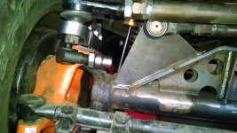
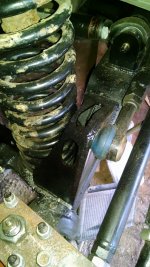
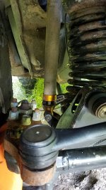
Next I wanted to start mocking up the steering. I knew I would have some potential issues and that did not "disappoint". I will need to move the TNT Track bar bracket back and center it more on the axle to clear the tie rod. It bends now, but not when it is DOM tubing :D
227636478_10113076681373182_3988131503619070078_n.jpg

So moving on from there for now until this 100+ degree weather breaks.... I got the H2 rims clearanced with some tool abuse. I used a flush router bit to "machine" the lip on inner hub hole to fit over the D60 axle shaft flanges.
228640754_10113079376077972_3506024431642357892_n.jpg

234803160_10113079376591942_690289454043036404_n.jpg

234836204_10113079376781562_248981352627979868_n.jpg

234570044_10113079377220682_3320396070699555511_n.jpg


I have the 37s mounted now and it is a roller for the first time in many years! Kind of rekindled the fire to work on this project haha.

236435150_10113084651670642_6161136335384127076_n.jpg

219652497_10113084651950082_4793168561355653510_n.jpg

231409075_10113084652444092_1673230739412701483_n.jpg

Decent Diff clearance.


Next on the list is to work out the steering. I have a longer pitman arm to install and then I will mock up the drag link. I also need to cut off the factory track bar bracket at the frame as well as the TNT truss bracket. I will have to slide those back, maybe even centered on the axle, in order to make things happy. I will have to play with the clearances while turning.

Such a long list of things to do yet... but I am liking the stance. I am going for 30% up travel and 70% droop to keep the COG low. :beer:
 
Nice to see.

I heard that all your welds will fail if you're not a cert carrying welder though so be careful. :laughing:
Not going to lie... I look at my welds and say "Those look fine" and then my brain starts with
"Yeah, they look good on the surface, but what is going on beneath? Did you get proper fusion? Are you sure? Are you over-confident? Are you going to have your truss snap off at highway speeds and veer off a mountain on fire?"

I hate my brain sometimes :laughing::lmao:
 
Good to see you back at this!
I too am a Pro-Crastinator! Haha, but in all seriousness, farm life, building a new house (and all following micro projects/expenses that follow) and things have just taken over for a few years. The wife wants to see it back on the road as well. Seeing it in person on wheels really changes things for me. It kind of rekindled that flame that I let burn out on it.
 
D_JEEPER Would a set of offset tie rod ends provide enough clearance for the trackbar bracket?
I would have to use 3 offset tie rod ends to push out the tie rod as well as the drag link. It did occur to me though and I have that as a last resort if it comes down to it... but I would REALLY prefer to not use those :)

I am waiting for my 7/8" heims to show up so I can mock up the track bar... but my plans this weekend are to cut the track bar bracket and slide it back about 3". I think that would give me all the clearance I would need. I thought about getting some tubing and just creating a tunnel for the tie rod to pass through but I can see that inducing a potential twisting moment vertically on that track bar bracket.

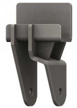
I did get a new frame side track bar bracket from Barnes4wd. I like how much beefier it is and it wraps 3 sides of the frame rather than the other one I bought that just tags on one side. This bracket will allow me to slide the exact mounting point around and adjust for any clearance issues.


I did some calculations and found that moving the track bar bracket 3" towards the axle would only induce about 5 degrees for the track bar. The forces induced outside of linear to the trackbar would only be about 0.83% so I might end up doing that. With dual heim joints, it should be just fine with that small amount of offset from perfectly inline.
 

Attachments

  • Capture.JPG
    Capture.JPG
    35.6 KB · Views: 30
Hey, I apologize if "all" my posts here sound critical of your work. I just went back and read through the thread trying to get a better understanding of your arrangement and noticed that I sounded critical in nearly all of them.
 
Hey, I apologize if "all" my posts here sound critical of your work. I just went back and read through the thread trying to get a better understanding of your arrangement and noticed that I sounded critical in nearly all of them.
First off.... critique helps me end up with a better product haha. Just because you think you are being critical doesn't mean I am receiving them as such :beer:
In this instance... what if I didn't know about offset TREs? That could have been a game changer if I was at a dead end.

Seriously, I am learning a bunch of this as I go so any sort of "Hey have you though about..." or "Why are you..." type of posts are constructive. If I cannot explain why I am doing something when asked then maybe I should rethink my position and approach.
 
Fair enough.

You might consider the following solutions in your quest for trackbar bracket placement.

I recently revised the brackets on my front 30 for my wife's XJ...

20210103_173428.jpg 20210109_180459.jpg 20210110_114032.jpg
 
This was my solution for another XJ, this time with tons...

I don't know if or how far rearward you can move the coil spring mounts, but any gained space will help in your TB placement.

2015-05-16.jpg IMG_20150802_155113274.jpg 20160828_141404.jpg
 
Why are you harping so much on me???? :laughing::flipoff2:
I like that idea. I will be pulling the axle out this weekend and playing around with how much space I have. I have my coils just about as far back as they can go without being in a permanent bow at ride height, but I can look into a shim wedge if this were to be my solution in the end.
 
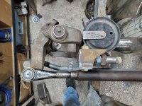
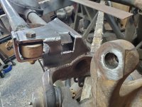
Well, I had a chance to break from the farm chores for a few hours this weekend. I cut off the old track bar bracket and reworked it to sit back about 3". This gave me enough clearance for a bolt head/nut or however I decide to set it up.
I really liked how the bracket tied into the front of the truss parallel to the axle tube. This would greatly relieve any potential lateral play in the bracket if I took a hard flop or something.

I had to figure out which steering direction made the tie rod closest and make my adjustments off of there. Glad I made a note of that because turning passenger was about an inch closer. :laughing:

240526796_10113118560342392_4150982189779111919_n.jpg

240184265_10113118560442192_2494687374113736485_n.jpg

240431384_10113118560551972_4495166836097182473_n.jpg


Now I just need to get out there tonight and burn it in. I also need to trim off the back part of the bracket some but I am going to do that after I weld it so I do not blow off the small overhanging tabs (if I were to cut it) on the back side of the truss.

Next step is cutting off the frame bracket.

The heims for the track bar were backordered but should be here Wednesday. Then I will start mocking all of that up and working on angles. :smokin:
 
Are you sure you're getting full swing in both directions?

Is your pitman straight (parallel to frame rails) at 0° steering?

I'd strongly advise tacking things for now, and waiting to burn it solid until you can check the geo/ clearance.

I'm REALLY bad at following that advce- LOL- it's bit me in the ass more than I care to admit. :(
 
Well, the pitman arm does not sit 0* when straight and I think that is to make up for the ackerman at full passenger? That is how it works out in my head anyways: At full passenger turn, the passenger tire swings more than the driver by some small amount, you need more pitman throw in that direction in order to compensate, since the drag link connects on that side.

Check my thinking on that one to see if it holds water. I might be conceptually wrong here
 
I had a write up on this exact situation on the "other" site... I'll paraphrase- the pitman needs to be as close to 0° with the wheels straight or you won't have full/ even steering angle. I'll look for the photo to illustrate the point.

EDIT- ok, the upper detail shows the pitman arm (PA) at straight/ 0°.
The bottom shows it clocked ~10° inboard of straight.
The CAD program I used didn't have the ability to show different positions as I would have liked, so I did the best I could.
Take note of the drag link lengths in the upper compared to the lower; once you think about it a bit it will make sense. (Actually- I just realized that my lower detail was dimensioned incorrectly- the upper dimension (with PA and steering knuckle at 0°) lands on the wrong hole at the high steer arm (HSA).
However, the indicated knuckle/ steering angles are correct.
I don't get into it, but there is a ratio between PA and HSA lengths that accounts for the observed difference in PA angle VS knuckle angle.

Feel free to PM me and I'll share my cell and we can talk it out.


Y_60 high steer arms.jpg
 
Last edited:
Ah this is good. I like numbers.... engage engineering brain.

So the pitman arm I am using will have the masters filed down so I should be able to index it as I need it to remove that 10 degree factory angle or whatever it is. I should be able to clock it tooth by tooth until I get where I need.

I went with a Moog K80795 pitman arm, which, I am almost certain, is offset different from the jeep pitman. I was informed about the pitman arm to steering arm ratio by one of the sales reps at PartsMike (Del Westerlund....Super helpful and informative dude! ). He warned me right up front that high steer on a TJ is a PITA to make work and might not be worth the effort. But I am a stubborn asshole and wanted to give it a shot and work through the kinks because I like pain or something :lmao::laughing:
This MOOG arm will put me at about 93% length. I might also need to do a motor mount lift for how close it is getting to the radiator hose but that is a challenge for future DJ.(I need new mounts anyways)
 
The (length of) PA to HSA ratio is not particularly critical IMO.

The clocking of the PA is fairly critical.
 
Top Back Refresh