What's new

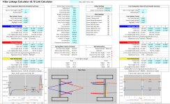
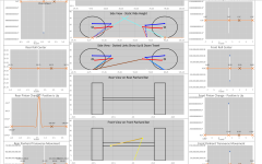
New Version of the 4 Link Calculator

Almost through the outputs for the link sizing page. Just got done fixing some of the math for the rod ends. I think I still have a little debugging to do for the factors of safety, but I think the issue is in the force calculations, not the factor of safety calculations.

YeeP Since you asked for the feature, I'll throw this question to you. Regarding the rod ends at the axle's direction, it makes sense that up travel is positive angle at the frame, but the sign at the axle is less straight forward. Currently, it is set up to use angled up as positive. This makes it display as shown below with it not lining up with the frame side. There are 2 other options:
  1. Having both up travels with the signs meaning positive is up travel
  2. Having both up travels on the right with the sign indicating sloping up or down as it currently does
1689473877004.png

I see how this could be confusing. I think that maybe the way that makes sense is the sign of the angle is based on the direction of the control arm connected to it and the direction it travels away from the joint. Viewing a chassis from the side where maybe the axle is fully compressed; the axle side upper would probably have the control arm heading "downward" away from the joint. In this instance a negative value would make sense in my mind.

EDIT: possibly the readme could say something like the angle being in reference to a line parallel to the ground?

Hope this helps.
 
Last edited:
I know Im pretty computer retarded but after downloading it and figuring out how to get it open it gives me "View Only" and wont let me input any numbers? :confused:

Edit: It will let you view only in the "free online version" of Excel
 
Last edited:
good am

is there a worksheet that can be printed and taken out to the shop and write in all the info then go back inside and use the computer to put in all the numbers. i think i can screen shot a few sections and make work. but just asking if that is an option.
thanks again
 
good am

is there a worksheet that can be printed and taken out to the shop and write in all the info then go back inside and use the computer to put in all the numbers. i think i can screen shot a few sections and make work. but just asking if that is an option.
thanks again
I've never made one. I would probably just write it down on a sheet of paper or make note of it in my phone.
 
I have started over with a fresh copy of the file already in an attempt to find where the calculation issue happens. I also have noticed that the front pinion calc is flat lined similar to the above.

EDIT:
Screenshots:
Screen Shot 2021-11-04 at 11.02.07 AM.png
Screen Shot 2021-11-04 at 11.02.19 AM.png
Screen Shot 2021-11-04 at 11.02.37 AM.png
Screen Shot 2021-11-04 at 11.03.02 AM.png
Hi, so I'm have pretty close to this same issue using excel 16. I've enabled macros, closed, reopened, etc.; but it hasn't changed anything. Any ideas? Thanks!
 
Can you post some screenshots?
Here you go, Hope this helps. A couple of things started working when I forced macros to be on, but the majority still doesn't. I'm thinking it's something dumb that I overlooked but I just couldn't figure it out. Thanks!
 

Attachments

  • Screenshot 2024-03-29 194533.png
    Screenshot 2024-03-29 194533.png
    106.8 KB · Views: 19
  • Screenshot 2024-03-29 194617.png
    Screenshot 2024-03-29 194617.png
    73.4 KB · Views: 21
Here you go, Hope this helps. A couple of things started working when I forced macros to be on, but the majority still doesn't. I'm thinking it's something dumb that I overlooked but I just couldn't figure it out. Thanks!
Hmm. That is weird. Can you share a screenshot of rear link calculations at the top of the Calculations tab?

Edit: I wonder if I used formulas that were not available in Excel 2016.
 
Hmm. That is weird. Can you share a screenshot of rear link calculations at the top of the Calculations tab?

Edit: I wonder if I used formulas that were not available in Excel 2016.
Hopefully these aren't so zoomed out that you can't read them. Is this what you needed?
 

Attachments

  • Screenshot 2024-03-30 191916a.png
    Screenshot 2024-03-30 191916a.png
    19.5 KB · Views: 9
  • Screenshot 2024-03-30 192141.png
    Screenshot 2024-03-30 192141.png
    30.5 KB · Views: 10
Well, I'm having a hard time finding a 5.0 download that works. I tried in Excel 365 Web based, which I have access to through work, but it turns out that the web version doesn't work either. I'll keep working on it and hopefully will find a way. Thanks for your help!
 
Not your fault at all. That’s Microsoft getting their money.
What I don't get is why Bill Gates chose to name his company after his pathetic dick.
 
So, it seems in non office 365 versions of Excel, that VBA functions cannot export to multiple cells.

It seems that this has some info on how to have it put stuff in multiple cells:VBA Help! Can a one cell function returning outputs to multiple cells?
Hey,

First of all, thank you so much for this great tool. I've used it to calculate suspension geometry for Ford 8.8 swap back in 2017 and now, working on front axle swap as well. Looking at the progress over the years, there's been a lot of hard work put in this project.

I was able to fix the calculations for Excel 2016 (win) with quite simple tricks: 1) On calculations sheet, select S17 to display the formula 2) extend selection to S17:V17 3) click formula to edit it 4) hit Control-Shift-Enter (as instructed in the "mrexcel.com" forum link above) 5) repeat for all columns that were not correctly parsed on row 17 6) select S17:CC17 7) copy-paste selection to S17:CC43 8) done!

Few trivial "bug fixes" for 6.10:
  • off by one: Shocks L16:L17,L24:25 reference wrong column in Calculations, should be K not L
  • Shocks E46 & O46 do not have correct formatting for mass like elsewhere
It may also work to extend the s17:v17 down instead of line by line.

Thanks for the bug finds I'll take a look at them.
 
I tried downloading the calculator, and its only downloading the edits of yours, I don't know how to operate excel, so, I may just be being an idiot.
 

Attachments

  • Capture calc.PNG
    Capture calc.PNG
    58.1 KB · Views: 13
I tried downloading the calculator, and its only downloading the edits of yours, I don't know how to operate excel, so, I may just be being an idiot.
The tabs along the bottom take you to different pages. You will also need to take it out of protected view and enable macros.
 
Delete this if I'm being a dumbass.....can I use the front suspension for beams (2wd Ford type stuff)?....I think the answer is no :flipoff2:
 
Delete this if I'm being a dumbass.....can I use the front suspension for beams (2wd Ford type stuff)?....I think the answer is no :flipoff2:
I think the answer is partially. It should be possible to use the calc to get an okay idea of what the anti's will do, front back movement, and caster change.
 
06h3 that information is super helpful, thank you.

Treefrog I did a bunch of research and it got a little math heavy so I started writing my own python code to calculate sway bar rates, max twist angles, forces, etc. I feel like you may find this code useful if you want to incorporate a sway bar sheet in your calculator.

Here’s the code:

#Sway Bar Calculator

#Inputs
sigma = 100 # Max Shear Stress (ksi)
G = 11600 # Shear Modulus (ksi)
L = 40 # Length Tip to Tip (inches)
OD = 1 # Outer diameter (inches)
ID = 0 # Inner diameter (inches), enter 0 if solid bar
A = 16 # Arm Length (inches), center to center
O = 2 # Arm Offset (inches), enter negative number for arms wider at sway bar side
Y = 44 # Distance between shock mounts at axle (inches)
T = 12 # Shock travel (inches)

#Setup
import math
pi = math.pi
L_w = L - 4 # Working Length

#Formulas
theta = 2 * L_w * sigma / (G * OD) # Max Twist Angle (radians)
theta_d = theta * 57.29578 # Convert from radians to degrees
J = pi/32 * (OD ** 4 - ID ** 4 ) # Polar Moment of Inertia (in^4)
tau = 1000 * J * G * theta / L_w # Torque at Max Twist Angle (in-lbs)
F = tau / A # Force at Max Twist Angle (lbs)
K = tau / (theta * A ** 2) # Sway bar rate (lbs/in)
flex = theta * A * Y / (L + 2 * O) # Max articulation (in)
lim = 100 * flex / T # Flex limited from sway bar (as percentage, >100%: sway bar does not limit flex)

#Outputs
print("Max Twist Angle =", round(theta_d,1), "°")
print("Force at Max Twist =", round(F,2), "lbs")
print("Sway Bar Rate =", round(K,1), "lbs/in")
print("Max Articulation (at shocks) =", round(flex,2), "in")
print("Usable Flex =", round(lim,1), "%")


For anyone else wanting to do their own calculations, all you need is a Python IDE (I’ve just been using www.online-python.com, it’s free and there’s no sign up or download), just copy/paste. Mess around with inputs and hit run.
I hope you do not mind me bringing calculator development stuff over hear.

I am not opposed to adding sway bar stuff in the future. Though I would most likely add it as part of a 3d movement viewer instead of a standalone tool in the calculator. The full travel envelop 3d code that I am not currently planning to release has part of it already. I took the route of solving for twist first. But, I have not gone as far as turning angle into torque or forces yet. I want to eventually get to the point of having a polar plot showing rings of gs of force vs change in chassis angle relative to the ground.

In seeing what sway bar calculators are out there, it seems that Triaged started one back in 2011, but the link to it is dead.

edit: I may throw together a simple standalone excel version of this at some point or you could do it.
 
Last edited:
How difficult would it be to add a tab to the four link calculator spreadsheet that shows front and rear axle wheel position when steering lock to lock? Initially, I had a front axle triangulated for link mocked up that would case the tires to crash against the lower links. It might be a great addition to the spreadsheet. I see the complications involved though, regarding not simply overall tire diameter, but wheel backspacing and WMS differences, etc. Maybe it's more complicated than it's worth. Thoughts?
Answering this here since it is tool development.

In general. it is an easy add. The hardest part is deciding how detailed to make it.

The way I do it in my full 3d tool uses KPI, camber, caster, and the side to side position of the u joint. Portal camber and caster are also accounted for when needed.

I do not know if it is a good idea to go that far on this tool. I think the best option is going to be the Y location of the U joint and the steering angle as inputs. The output would be if the center of the link hits the tire and if not, the distance from the centerline to the edge of the wheel.
 
Top Back Refresh