What's new

MCI 102-C3 coach to RV - Engine Bay

Couplers is all that's holding me up on what pump to mount. It'll be a VTM42 or V10. The VTM42 tops out at 2,000psi and more than handles the RPM. The V10 tops out at 2,500psi and I'm limited to the 0.2, 0.4, or 0.6 cubic inch to handle the RPM. The V10 pilot is 0.5" larger than what the housing allows, but there's more than enough material to allow the bore to be opened up and the machining process would be simple. Honestly, I can just ream it out with the die grinder because the pilot isn't used to center the pump.
 
aczlan said,
JNHEscher said:
Couplers is all that's holding me up on what pump to mount. It'll be a VTM42 or V10. The VTM42 tops out at 2,000psi and more than handles the RPM. The V10 tops out at 2,500psi and I'm limited to the 0.2, 0.4, or 0.6 cubic inch to handle the RPM. The V10 pilot is 0.5" larger than what the housing allows, but there's more than enough material to allow the bore to be opened up and the machining process would be simple. Honestly, I can just ream it out with the die grinder because the pilot isn't used to center the pump.​
Will you need anything else run off of the engine? If so, would it be worth putting an accessory drive pulley on and belt driving the pump off of that?

If not, is that still a SAE 2 A mounting flange?
If so, it looks almost like you could make an adapter plate (that would weld in place of the "tangs") and weld on a shaft/coupler to push the pump connection back far enough that you can drive a "regular" pump off of the 3 bolt drive, something like
https://www.surpluscenter.com/Power-...027-1-1495.axd
5+8+9T+Splined+Coupling+03-32-00027_M.jpg

or:
https://www.surpluscenter.com/Power-...r-1-1563-B.axd
5+8+Shaft+Coupler_M.jpg

Then you could use any "standard" SAE 2 A pump

Speaking of drive hubs with tangs, did you see this one for $17ish? https://www.ebay.com/itm/OEM-Detroit...s/223188573421

Aaron Z
 
CarterKaft said,
JNHEscher said:
Couplers is all that's holding me up on what pump to mount. It'll be a VTM42 or V10. The VTM42 tops out at 2,000psi and more than handles the RPM. The V10 tops out at 2,500psi and I'm limited to the 0.2, 0.4, or 0.6 cubic inch to handle the RPM. The V10 pilot is 0.5" larger than what the housing allows, but there's more than enough material to allow the bore to be opened up and the machining process would be simple. Honestly, I can just ream it out with the die grinder because the pilot isn't used to center the pump.​
If you get a splined drive coupler I think you could run any pump you want even the stacked pumps talked about earlier.
 
Yep, the mounting flange here is SAE A. So "claw coupler". Any pump with and SAE A flange will fit right on. All I need to find is the particular halves of the claw coupler I need to fit and engage with the other half that is the blower drive hub along with fitting the splined or keyed shaft on whatever pump I match for this. I'm not getting any results on couplers for the Vickers pumps, so I think I'll call Luke on this one to hopefully get some names or numbers of couplers that will work. There only being two tangs, I would assume there's a spider in there.

The hubs for the blower and power steering have different part numbers cast into them, although they look like the same hub. I don't yet have any info on whether or not they're interchangeable. The major difference being that the blower drive hub has the splines for the mid shaft that drives the blower itself and the steering pump hub has a smooth bore. No splines for the blower = non-running engine.


Update: Hot damn, Facebook is still good for something. Luke spotted my post and knew exactly what I was after. $75 shipped for the coupler and spider and they're headed my way today. The coupler is for a 3/4" keyed shaft and Luke said all the steering pumps have been that way on these buses. Might as well keep it common.
 
bigun said,
JNHEscher said:
Update: Hot damn, Facebook is still good for something. Luke spotted my post and knew exactly what I was after. $75 shipped for the coupler and spider and they're headed my way today. The coupler is for a 3/4" keyed shaft and Luke said all the steering pumps have been that way on these buses. Might as well keep it common.​
Sweet! :smokin:
 
87manche said,

so full steam ahead on hydraulic cooing fans?

I like it. Way better than figuring out how to keep thousands of watts of e fans working properly.
 
87manche said:
so full steam ahead on hydraulic cooing fans?

I like it. Way better than figuring out how to keep thousands of watts of e fans working properly.​
Full steam ahead. Earlier, my reason for disliking hydraulic was because of how frequently they’ve failed and been replaced by electric on cars. This being a commercial application and using a ton of common, reasonably priced parts makes it all the worthwhile. So the advantage of hydraulic power and efficiency is coming to life here. The fact there was indeed another place to mount an SAE accessory made my day. Now I just need to officially decided the radiator placement.
 
I tried out the Eccotemp L5 in the yard today. Unimpressive because I couldn't get enough fuel through it. That and the hot water was pushing through 25 feet of garden hose laying on frozen ground. Gonna swap regulators because the other one I modified put out some major heat.

I flushed out the last bit of coolant and some sediment with the warm water to start off with. Pulled the water out with the shop vac and ran this $10 hair dryer for a few hours. I tested the hair dryer a few weeks ago and it did really well. Just went out to shut it off and even the heads were warm as we're dipping in to the single-digit temps tonight. $10 well spent.

405.jpg
 
Beating this subject to death, but it doesn't hurt to plan every detail. Measure 60 times, cut once, right? Played around with the cores a little more and I think I'm really digging this arrangement the most. On the caps, there's two pins. The pins on one end are 5-1/8" apart. On the other end, they're 4-3/8" apart. This separation must signify a top and bottom. Alternating the cores by top and bottom bunches them closer together, allows more center support "contact" for greater fastening, and appears that it would still allow plenty of breathability. I'm not really sure that they're aren't designed to be mounted like this anyway. The fins on these are pretty tight, so I don't want to wedge the cores too closely together.

In this arrangement, the ports are 2-5/8" between centers and core pairs occupy 5-1/4", meaning I can very easily fit eight cores together per side and mount them vertically. Even better is that the total width comes to 21" and the distance between the center support and each end of the core is 20-1/2". How's that for sizing fans?! A pair of fans or two pairs for push and pull per left and right radiators without any awkward shroud sizing.

With that said, I need to consider whether or not a pair 20"/21" fans will hammer enough wind through these. Including all faces exposed the fan when using eight cores per radiator, each fan would be covering 1,154 sq. in. I'll be calling EFE. Got a hunch they won't give me much info and charge a hellacious price. If that's the case, to piecing my own fans together I go.

408.jpg
409.jpg
 
For shits n grins since I can’t get anyone on the phone at this hour or until Monday morning. I suppose there’s a cfm per rpm range chart on this bugger somewhere.

410.jpg
 
87manche said,

you will have to do math.

figure out the velocity of the air column given the pitch at a given RPM. Then figure out the swept area of the fan. then take a WAG at the slip numbers because no prop is 100% efficient and arrive at a reasonable number.

no different than calculating the theoretical thrust of an aircraft prop and power system.
 
On that "thetruckstop" site, a member mentions Hoverhawk. Very familiar site. I somehow stumbled across them years ago while I was messing around with Northstar engines and had some brief interest in hovercraft. I think I'll call them first. The more I dig into EFE, the less I care for them, but I'm curious to hear what they say.
 
Called Hoverhawk. Their fan hub options include bolt flanges and keyed shaft. Keyed shaft would be great for using the same couplers as what the pump uses for direct drive without direct mounting.

Went sifting through their fan listing. I think I'll be alright with this, keeping in mind that there will be four puller fans -
22 inch diameter, Type 3, 8 blades, 3600 rpm, at stated blade pitch produces:
25 degrees, 9,250 CFM, 17.5 pounds, using 4.7 HP
30 degrees, 11,500 CFM, 23 pounds, using 6.5 HP
35 degrees, 14,700 CFM, 34 pounds, using 9.7 HP
40 degrees, 16,600 CFM, 41 pounds, using 12.6 HP
45 degrees, 19,500 CFM, 54 pounds, using 18.4 HP
50 degrees, 21,400 CFM, 64 pounds, using 23.3 HP
Weight, 5 pounds, Cost $179 USD plus shipping.

Adjustable blade pitch would be cool for a bit of tuning, although I'm sure I would be setting the pitch as steep as it would go. Fixed blade fans are 3-4 pounds lighter. They can spin as high as 3800rpm. Even higher, I'm sure, but 3600 is what they should spin at for cruising speed in a thrust application, so I suspect there's efficiency of air movement in the equation.
 
CarterKaft said,

Not having a clue about fan speeds for cooling or thrust for that matter but 3600 RPM is gonna be hella loud and taxing on pumps/motors I bet.

I can't think of any of our fans that are much over 2k rpm. Not saying you don't need that much speed but maybe cross check the flow a static pressure if possible to determine if you can go higher pitch at slower speed.
 
CarterKaft said:
Not having a clue about fan speeds for cooling or thrust for that matter but 3600 RPM is gonna be hella loud and taxing on pumps/motors I bet.

I can't think of any of our fans that are much over 2k rpm. Not saying you don't need that much speed but maybe cross check the flow a static pressure if possible to determine if you can go higher pitch at slower speed.

Sent from my SM-G950U using Tapatalk​
I don't doubt these would make the sound and wind of a hurricane. Mainly stating their max speed for discussion purposes and wanted to include the spec sheet. The lower the rpm that I can get sufficient cooling out of, the better. The pumps and motors I've been browsing have a max rpm of 3k-5k and the pump drive will spin at 5k if the engine is revved to its redline. I want to be sure that all components can handle the speeds they might see.

They have a 9-blade 24". With some structure relocating, I can fit that. That's a type 4 adjustable. Costlier, but I could play with blade pitch all I want and possibly compromise between air velocity/pressure and hydrostatic load where needed.
87manche said:
the steeper the blade pitch the less efficient it is.

get the least pitch possible to accomplish the CFM goals.​
25 degrees is the shallowest pitch they show, though I'm curious if the adjustable hubs allow for anything beyond that or if they have stops. I would think the blade mounts would be keyed or splined to be sure that all blades were set at the same pitch. Kinda comes down to choosing the largest diameter fan I can fit with the highest blade count available.
 
CarterKaft said,

Right on, you are on the same track.

Something I didn't think about is diameter, are fans (most) are allot larger than that.
I can think of some smaller applications though, Ill check their speeds.
 
87manche said,
JNHEscher said:
25 degrees is the shallowest pitch they show, though I'm curious if the adjustable hubs allow for anything beyond that or if they have stops. I would think the blade mounts would be keyed or splined to be sure that all blades were set at the same pitch. Kinda comes down to choosing the largest diameter fan I can fit with the highest blade count available.​
higher blade counts are also less efficient. The most efficient prop would actually be a single blade with a hub mounted counterweight, it's just completely impractical because it would be heavy and probably far too long to be practical.

adjustable pitch would be a good thing, since we're taking shots in the dark here on how much airflow you need, and we can't really accurately calculate the flow restrictons of your cores because we don't know the orientation/shrouding situation until you build it, and by that time it's too late.

I'm not trying to be a downer, or second guess your decisions, just here to tell you what I know about props, which is significantly more than the average person, but probably less than an aerospace engineer.
 
CarterKaft said:
Right on, you are on the same track.

Something I didn't think about is diameter, are fans (most) are allot larger than that.
I can think of some smaller applications though, Ill check their speeds.​
Much appreciated. I haven't searched fan speeds on commercial applications yet. Got a feeling there isn't much info out there on it.

87manche said:
higher blade counts are also less efficient. The most efficient prop would actually be a single blade with a hub mounted counterweight, it's just completely impractical because it would be heavy and probably far too long to be practical.

adjustable pitch would be a good thing, since we're taking shots in the dark here on how much airflow you need, and we can't really accurately calculate the flow restrictons of your cores because we don't know the orientation/shrouding situation until you build it, and by that time it's too late.

I'm not trying to be a downer, or second guess your decisions, just here to tell you what I know about props, which is significantly more than the average person, but probably less than an aerospace engineer.
Click to expand...​
Bring it on. As far as I know, nobody has set this up on any of these buses and I'm open to all good knowledge. By the time I studied and learned everything there is to know about fans, I might as well apply for a job in some division of aerospace engineering. I know I'll only be picking what is assumed to be best and have to give it a go. If you don't mind, add in some of what you know about what separate efficient from inefficient prop designs. I was reading that fewer blades is better, but also read that more is better which is seriously putting a bind in my understanding of it all.

Hoverhawk does offer fans with as few a three blades. Many of their four-blade props are on eight-blade hubs. Any chance to minimize rotating mass should ease up the stress on the motors.

There's only so much air than can be pulled through the cores. The fins are 0.011" steel and gapped at 0.023". Wish they weren't quite that tight, but I'd say the need to be because of the folded design. The cores are single row and they bunch together in the same manner that an air filter does for maximum air flow in a confined area.
 
87manche said,

that is an interesting question.

so what makes a multi blade prop inefficient is the fact that every blade is following in the turbulent air of the blade in front of it. So a two blade prop is more efficient than a 4 blade prop, simply because there's less turbulence for each blade to encounter on each revolution. Cleaner air=efficiency.
but there are practical restrictions to that. You have to have enough blade area to transmit the horsepower of your engine to the air. So you get into a compromise where efficiency is sacrificed for practicality.

So as a starting point I'd figure on how much HP you can generate with the hydraulic motors, what RPM you want them to run at, and what space constraints you have for the fan diameter.
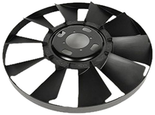
Once you have those basic questions answered you can start to think about fan size and the amount of blades you need. If you only make 10 HP, then getting a 8 blade fan that can take 25 is just hurting your efficiency. You should get a 4 blade fan that's maxed out at the power you can drive it with, and it will be the most efficient choice.
This is pretty much how I prop airplanes these days. With electric power systems it's easy to know your input wattage, and therefore how large a prop you can spin. Then you've also got to take into account your desired speed envelope so you can pitch it right. Of course when you increase the pitch you have to decrease the diameter, or you can't spin it to your desired RPM, because you put too much prop on it and you don't have the power. Then you have to make sure it's going to clear everything. So sometimes I end up with a less efficient steeply pitched prop and eat the efficiency penalty because I don't have the clearance for a larger unit. My seamaster is propped with a 3 blade, because I can't put 3HP through a 2 bladed prop in the space I have between the motor pod and the fuselage. She sings good, which is a sure sign that I'm not in the happy zone for the prop, but no fucks given, that's a brute force approach.
here, listen to the bastard
https://www.youtube.com/watch?v=-i6Ey8IT-m8&t=


you're also going to want to do some basic diameter/rpm math so that you can figure out tip speed. if at any point the tips go supersonic, massive hit to efficiency and flow.

This is a big reason for swept tip props. In the transonic range they don't take the performance hit that a straight blade would because the shockwaves that are beginning to develop "slip" off the end of the prop.

so summary, because I got a little off track there.
the most efficient fan you can put on there is the one with the largest diameter, least amount of blades and least amount of pitch that can take all of the motor's power while applying enough load to keep your motor from overspeeding, or running up against it's own governor.
We adjust that as other constraints demand. So figure out how much power your hydrualic system can supply, either in HP or watts, and then we can make some semi educated guesses as to what size fan matches up to your power. I'll dig up my prop calculation software.
 
Yesterday, I concluded on what would be the official core arrangement and location. I may draw it in CAD so it's easier to visualize, but I'll go ahead with a description and hopefully be thorough enough.

With eight cores per radiator fastened together like I had pictured the other night, the overall dimensions make for easy mounting and a crap load of cooling surface area. Width and depth come to 21"x6-1/2". Length is dependent on end tank sizes. Mounting both assembled cores end to end horizontally fits right in the width of the bus that is available.

Twelve cores may very well be plenty. Probably going ahead with sixteen so that I don't short myself on cooling capacity. The fans will be a minimum of 20" in diameter anyway. I would still like to compare fluid volume between the OE rads and the Micon cores. I ran a few number to determine how many folded cores it would take to equal the port flow of the OE rads. Two weren't enough and three were more than enough.

So, horizontal mounting totaling the width of two main cores (85"+end tanks), an end tank on each at the furthest ends and a central, shared tank in between them. The center tank will be split for dual pass. Mounting this way cuts costs down fairly significantly and brings the radiator hoses right above the engine. I'll be T'ing the t-stat housing outputs together. The manual may state a reason that these were designed with a separate t-stat for each head, but I like the idea of both heads being able to flow into all the cores. I think they only did that because of the dual radiators.

We agreed that extra storage space where the radiator fan used to be wasn't that big of a deal and I couldn't get past the fact that the radiators could get damaged in a collision if they were mounted vertically because they would hang so low. These buses are stout, but the occurrence of cars slamming into corners is becoming more frequent (dumbass drivers keep multiplying!). Placing the cores back up top brings me back to poor air flow. I have to measure the openings and cavity to be sure I can get enough hair volume in there. The folded cores and scoops should help mitigate this problem that the original setup dealt with.

Horizontal mounting still accommodates four fans to cover all of the core area. I'm still guessing that I'll use one motor per fan. One motor to drive a belt that runs all four fans doesn't sound like the best idea. Driving the motors in series is going to be the most simplistic plumbing configuration I can think of and produce less heat than anything else. With four motors, I'm thinking two stacked pumps would be smart. One pump for two motors.
 
Hoverhawk actually has a tip speed calculator on their site which is really nice. I was punching in my numbers and kept coming in at around half of what their recommended max speed is because I'm running a 20"-24" prop.

Once I get the accessory pump coupler piece, I'll confirm the pump shaft size it fits and lay out all my pump options to sort HP from. I'm not opposed to having the coupler bored out to fit a larger shaft or press fit a splined coupler that I can weld into it.
 
I'll call Hoverhawk again tomorrow. I'd like to know if the fixed blade hubs allow blades to be removed. If so, I could go ahead with an eight-blade fan and run two, four, or eight blades. Also what size shaft the keyed shaft hubs are made for.

More in-depth reading shed a lot of light, but also became more a of crapshoot. Take your pick, essentially. More or less blades, more or less pitch, etc. I'll see what I can get in the way of an eight-blade type 4 or 5 adjustable pitch fan in the 20" flavor. Seems best to load up on fan options since the radiator cores are an absolute. With a fan chosen, I'll see if I can get HP requirements in each blade configuration within an RPM range. 500-2,000rpm?
 
CarterKaft said,

Damn, great fan discussion, allot of info for a guy like me that doesn't know squat about fans...

I looked at a aftercooler fan last night on a 745C articulated truck. The fan/cooler are mounted conventionally in front of the engine on the front of the truck but only cools the Aftercooler core and A/C condensor. It is a 8 blade 24" diameter sucker but at the moment I cannot find the RPM speeds for it only the larger rear mounted radiator fan.
 
87manche said,

all the hovercraft stuff is rated at 3600 rpm because that's standard governed speed for a small engine.

the adjustable hubs would allow tweaking afterwards, and may be worth the extra cost.
Do you have an optical tachometer?
 
Luke's parts arrived. The blower drive hub I ordered off ebay is marked shipped but I haven't gotten tracking. I was relieved to know that Luke had this stuff. The coupler half looks pretty specific to the engine. Should've ordered to entire coupler from Luke. I can't measure for pump shaft length until I get the drive hub.

Coupler bore is 3/4" straight with 3/16" keyway. OD is 1.335", allowing plenty of room to enlarge the bore for other pump shaft options. One person told me that there was a fiber disc in between that would break in case of a seized pump. There is indeed a fiber disc (spider), but if the pump ever seized and the spider broke, the blower drive hub would still spin and the tangs would find each other again. That same person also started their comment with "I was told..". Oy vey, the internet rumors.

411.jpg
 
CarterKaft said:
Damn, great fan discussion, allot of info for a guy like me that doesn't know squat about fans...

I looked at a aftercooler fan last night on a 745C articulated truck. The fan/cooler are mounted conventionally in front of the engine on the front of the truck but only cools the Aftercooler core and A/C condensor. It is a 8 blade 24" diameter sucker but at the moment I cannot find the RPM speeds for it only the larger rear mounted radiator fan.​
Got me curious why they went with 8 blades. From what I can make of all the propeller tech, more blades make for more thrust and efficiency at lower RPMs.
87manche said:
all the hovercraft stuff is rated at 3600 rpm because that's standard governed speed for a small engine.

the adjustable hubs would allow tweaking afterwards, and may be worth the extra cost.
Do you have an optical tachometer?​
Just like my four banger subie that has to spin at 3700 on the interstate to cruise with traffic. Annoying lol.

No tach in my possession. I will be getting one because I've needed one enough times now to warrant the purchase. Gonna go with a high blade count with adjustment so I can change up either one without a fuss since I have no decent way of determining the restriction or actual flow until I have fans mounted and running.
 
87manche said,

I'm not sure how 3600 RPM became the standard speed for small engines, but that's just the why.

optical tach will help us tune it for max RPM, and with an IR temp gun we should be able to judge how hard the motor is working.
should be able to get it dialed in pretty well from an efficiency standpoint. Then you can adjust for more airflow if needed.
 
Top Back Refresh