JohnnyJ
Low Range Drifter
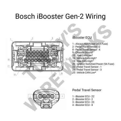
I don't have wire colors, but it seems like you should have pin 20 going to ignition. I'm guessing purple as it's just 5A. I'd guess the 12G is the 40amp fused on pin 1.
Follow along with the video below to see how to install our site as a web app on your home screen.
Note: This feature may not be available in some browsers.
If you connect Pin 20 and Pin 1 together to your kill switch then the kill switch still kills power to everything, and then the brakes turn on with only the kill switch being on.I don't have wire colors, but it seems like you should have pin 20 going to ignition. I'm guessing purple as it's just 5A. I'd guess the 12G is the 40amp fused on pin 1.

Keep in mind the diagram is from one side. Looking at the plug harness everything is reversed.I don't have wire colors, but it seems like you should have pin 20 going to ignition. I'm guessing purple as it's just 5A. I'd guess the 12G is the 40amp fused on pin 1.

That’s exactly how and why I ran it.If you connect Pin 20 and Pin 1 together to your kill switch then the kill switch still kills power to everything, and then the brakes turn on with only the kill switch being on.
That's how mine is setup, and presumably how Hydrodynamics is from his description. The ignition wire is to stop it drawing power and killing the battery, which on a buggy is kind of pointless since you'll just hit the kill switch and disconnect the power to everything when you turn it off unlike a street vehicle.
Keep in mind the diagram is from one side. Looking at the plug harness everything is reversed.
Doesn't matter in 4x4 without a center diff.Quick question: I assumed since it was a passenger car, it was setup diagonal lines with a distribution block; so I just put front brakes to front port. Is that how everybody else is doing it?
Doesn't matter in 4x4 without a center diff.
I assume voltage will affect max pressure? Maybe only flow rate.Sure, but if it makes a difference on street driving, I'd swap them.
With some solo brake bleeding I'm sitting at 1150-1200 psi. Good enough for now. Will need to clean up some wiring and maybe take it for a drive to see how it feels.
I assume voltage will affect max pressure? Maybe only flow rate.
Would I buy the pigtail for 2x the cost or do another of these? I'd likely buy the pigtail. This was kind of a PITA, but doable.
I assumed since it was a passenger car, it was setup diagonal lines with a distribution block; so I just put front brakes to front port. Is that how everybody else is doing it? Won't be a big change if I should flop. Off to go bleed.
snivilous- how are you plumbed?
I took it for a test drive tonight around the block in 2wd. With no prop valve in the back, the rear locks up first. In some ways not shock since I'm around 60/40 weight bias. Calipers are about the same volume and pad area, so trying to figure out without extra work if I switched ports if it'd make any difference. I can also step up to a slightly larger caliper up front and see if that makes a difference.
With the rear prop'd down, I was able to get the fronts to lock first. I've never locked my brakes on the buggy before, so definitely getting plenty of pressure.
IIRC, "standard" is that the rear most port on the MC (closest to the booster) is for the front brakes... Likely depends on the master, but it's been fairly consistent in my experience.The furthest port from the booster going to the front axle. I thought I had found that orientation being factory somewhere, but it's been so long I don't know the specifics. It's how my Hilux is plumbed, so the buggy and FJ I just copied that. I don't know if there's any internal bias, never measured or tried a proportioning valve but also never felt the need to adjust the bias.
I have a super duty master sitting here and that appears how this is setup since it has different size ports and the larger fluid port (presumably the front brakes) is the closest to the booster. So you're probably right.IIRC, "standard" is that the rear most port on the MC (closest to the booster) is for the front brakes... Likely depends on the master, but it's been fairly consistent in my experience.
outputs may be the same, but is the piston size inside the master the same for both ports?I have a super duty master sitting here and that appears how this is setup since it has different size ports and the larger fluid port (presumably the front brakes) is the closest to the booster. So you're probably right.
I don't know if it matters (as much/if at all) if the output ports are the same size. If I install this super duty master I'll definitely be flipping the lines though.
IIRC, "standard" is that the rear most port on the MC (closest to the booster) is for the front brakes... Likely depends on the master, but it's been fairly consistent in my experience.
Subaru vehicles use a dual-diagonal brake system that employs a master cylinder to feed a crisscross hydraulic circuit consisting of a primary circuit and a secondary circuit.
Braking force is transmitted to the right front and left rear brakes by the primary system while the left front and right rear brakes are fed by the secondary system. This style of system provides the safety of separate circuits and creates balanced braking in the event of a failure in one of the two circuits.
Common on all Japanese vehicles since the 90s.For modern passenger cars, many use diagonal splits.
outputs may be the same, but is the piston size inside the master the same for both ports?
It's not plug and play.And in other news I scanned the super duty master after confirming it's plug and play with the ibooster. I'll get the CAD uploaded in the near future.
And it is an absolute chunker by comparison. Very cool that (if you have the room) it's two nuts and swap fittings and you can completely reconfigure the brakes for pretty cheap.
Every Grumman step van I've ever looked under the hood of has a right angle adapter like that in it. Tons of people doing desert go-fast shit have used it or copied it to keep the brakes from wanting to occupy the same space as the coilover or shock tower.This could be a good way to mount an iBooster
For lights, use a wilwood prop valve… built in switch? Assuming normally open and when it sees pressure the switch closes and the lights turn on? Can’t get more simple than that…Has anyone found an easy brake switch solution? Maybe amperage based switch?
Did you get this sorted?Ugh. Two wires on the pressure sensor have slipped the crimp. Backup plan #1 is that I found a trailer brake harness on the shelf that uses a similar enough pin, but the connector housing is different. I can heat shrink the pins and slip them in and maybe rig up something to make sure they stay on. Plan #2 is I ordered a Bosch map sensor harness pigtail that looks very similar from the jungle website that should be here tomorrow. If that plugs in, I'll splice it into what I have.
What a PITA. I wish I could have found a factory pigtail when I was getting my unit.
This fits.
"Compatible with Polaris Ranger 700 800 900 RZR 1000 T-Map (Temperature-Manifold Air Pressure) Sensor Pigtail Harness Repair Wire New"