What's new

1989 Jeep Cherokee 1 ton swap

Rear axle went into the Jeep over Labor Day weekend 2021.

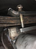
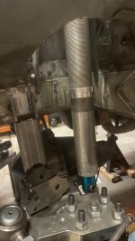
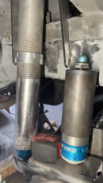
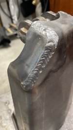
Pinion angle set. Tack welded the Ruffstuff +2 perch kit into place. Bolts must be cut to length because the rear bolts are directly above the axle.

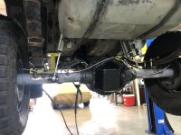
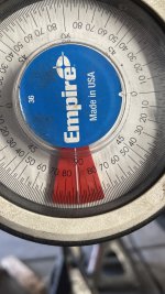
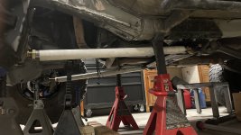
Pinion angle is about 3 degrees less than the driveshaft. Oddly, I paid $300 for a driveshaft shop in Carson City to put the flange on this and I THOUGHT cut it to length. When I pulled it out of the Dana 35 it was fully compressed with ZERO slip extension AT FULL DROOP. Stupid me must have never looked at it. I wonder how many problems it’s caused.

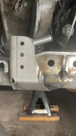
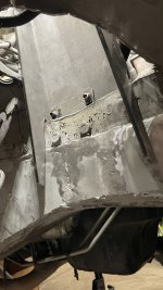
The plus 2 perch kit will probably work out great and now I’m wondering what I’ll do for bump stops. The factory ones obviously won’t work anymore. Bump stops might work if I weld some 3/16” plate to the rear unibody ‘frame’ to distribute the stress. A four link would PROBABLY fit but I don’t even know where to begin to plan out a 4 link. I will need to cut and fold the rear for sure and cut the wheel wells to fit a set of 35s I picked up.


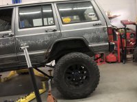
35s on an 18” wheel from a dodge truck. Cheap knockoff tires the guy said wouldn’t balance. I think they were spray painted black otherwise they’re just cheap coated black wheels.


1648826209710.jpeg


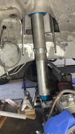
First install of the rear axle. Pinion was set to match the transfer case angle. This was way too low and just looked wrong. If you look close you can see the bolt in the spring perch going straight into the axle. I didn’t know these would require cutting the bolts when I bought them. I might suck at reading comprehension.
1648826244781.jpeg


Surprisingly the rear end isn’t much wider than the front. I should actually measure it to get an exact difference because now I’m curious. On a 13.5” wide tire the tire stick out about halfway so ~6 3/4” on each side. The fronts are a 12.5 for reference.
1648826303171.jpeg


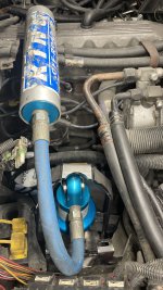
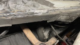
Pinion angle set using the stupid long driveshaft. It might work for light driving when I move the rear axle back an inch or two. I put in a 1310/1350 combination u joint just to make it work short term. If you look closely you can see where I burned through the frame welding frame stiffeners on.
1648826352154.jpeg


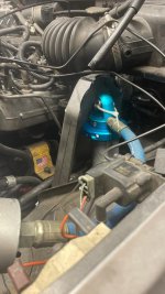
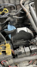
The poor quality photos are because the rear camera on my phone broke (dropped the phone too many times) and the front facing is all I have until I get a new one.
 
More photos

Full weight on the rear
Front on 33s
Rear axle moved back 1 inch.
this actually fixed my death wobble. So it must have been a caster issue.
MAH is HAM spelled backwards. Because front facing camera.


Snapped one of the grade 8 bolts last night. My own dumb fault for never chasing threads. I’m going to try drilling and retapping. I ended up welding the nut onto the bottom of the leaf spring perch and sending it.


Also found out ‘someone’ (me) bent the ears on the driveshaft slip yoke installing a u joint (see bigger tools above) so it’s either $225 for a driveshaft I’ll end up replacing, OR a brand new 2 5/8” 0.095 wall thickness 1350 CV driveshaft (plus tax obviously) from Drive Line & Gear in Sparks.
I’m honestly leaning towards just biting the bullet and buying the more expensive shaft. Paying $225 to have this one work short term seems like a waste of $225. Buy once, cry once. Never enough money to do it right the first time, but always enough money to do it twice.

Maybe I’ll move the axle forward an inch and see what the length needs to be then. Probably smarter to go with the ‘mama bear’ extension driveshaft measurement (2”) instead of baby bear (1”) or papa bear (3”).

Also, I’m thinking my 4” Rough Country leaf springs are limiting up travel because they’re stiff. I might cut off the shock mounts and move them so the shocks are more vertical and see if it flexes more. Using a 2 post lift and dropping the 35” tire on a Jack stand really doesn’t get me as much flex as I’m expecting. I’m honestly expecting it to contact the body, but maybe I’m stupid and that much leverage on the outside tire should be enough to stuff the tire as much as possible. I mean…I had the Jeep lifted enough off the lift to think it was about to fall off until I stopped lowering it and leaned on the Jeep. HARD.
it’s actually just the shitty shackle angle stock Jeep’s come with. Some relocated rear leaf spring mounts, or a 4 link, would fix this. Rear axle with locker installed. Then I drove it about 2 miles, heard a funny noise, and realized I NEVER PUT ANY GEAR OIL IN IN. true story.
 

Attachments

  • 1648826391709.jpeg
    1648826391709.jpeg
    595.3 KB · Views: 32
  • 1648826443125.jpeg
    1648826443125.jpeg
    737.9 KB · Views: 34
  • 1648826477479.jpeg
    1648826477479.jpeg
    1.1 MB · Views: 33
March 13, 2022

1648826686522.jpeg


1648826707419.jpeg


1648826722396.jpeg


1648826744465.jpeg


Passenger side frame stiffener was installed previously. I thought I was saving myself time. I wasn’t, but I got some experience welding. The unibody seems thicker up here and SLIGHTLY easier to weld to.
 
  • Like
Reactions: Add
Track bar mount welded on. If you look close you’ll see a good weld, and right next to it you’ll see a bunch of welding trying to cover up worse welding. It’s also welded underneath and I rotated the axle to make THAT welding easier. This also notched into the upper portion of the truss on the left hand side.

I need to drill the holes out because the heim is a 5/8” hole and Artec built this for a stock/aftermarket track bar which is 9/16 apparently.

I also customized this. Since I have a 7/8” x 3/4” (I think. It’s 12am. I’m tired and not going to measure it) and I used the FK misalignment spacers it was wider than the 1.5” Artec designed. All I really had to do is recurve the pieces to sit deeper on the axle. I went slow and took my time with lots of measuring. Thankfully I didn’t weld this entire truss up the day I learned to weld. I’d be so mad.
 

Attachments

  • 1648826833447.jpeg
    1648826833447.jpeg
    71 KB · Views: 25
Current status.
Shock towers from ruff stuff. The 9 inch ones. I didn’t think I’d want to cut through the good for the taller ones to fit, and I was concerned about the uptravel of the axle smashing into the steering or oil pan. i have no idea what i can do to limit up travel at this point.
I have no clue what I’m doing. I cut a lot out. I cut down to the top of the Moyer mount brackets on the unibody. My plan is to now not h the shock towers a lot so they sit lower. The coilover is fully compressed and the tower needs to come down about 2” at a minimum or else I will need to cut a LOT more of the fenders. I’d rather NOT cut the entire fenders out at this moment. I know doing so would make fitting tires slightly easier. It would also put my drag link at an upward angle and I think that’s too much stress on the steering box, pitman arm, and drag link end (1 ton Chevy tie rod) for zero reason other than I think it would look overatressed.

Ihave no clue how much that stuff can flex or handle. Maybe an upward angling drag link works just fine.

I need to figure out bump stops. Maybe the 2” ones I bought will magically fit. Maybe I need to build some kind of tall extension off the axle/truss to make them work. I still don’t have springs on so those will take up some usable area. these are 14” 2.5 coilovers in case anyone reading this forgot.

I’m open to any ideas anyone might have based on experience, etc.
 

Attachments

  • 1648826861289.jpeg
    1648826861289.jpeg
    79.9 KB · Views: 32
  • 1648826985331.jpeg
    1648826985331.jpeg
    72.2 KB · Views: 33
This is how much space I have from the well work 40” tire I mounted to the body. This is at full bump (axle center 22” above garage floor) so I’m confident I could fit a new pair if this is where the axle lives. It’s measuring 106” wheelbase using tape measures and eyeballs to determine center to center. Super accurate, I know.

I’m not sure I can cut this nub off so I’m just leaving it. The front bumper will need to be cut a fair amount to match this clearance. The rears will need to be chopped one day. I have no idea how much this wheel will rub my mink bar, and I’m HOPING Artec planning on a 1 ton swap running 40s. Perhaps they thought I’d run 37s. MAAAAAYBE 38s. I can’t bend tube so I’d have to build a link, take it to someone who CAN then use that link.

still trying to figure out the best way to make sure this axle is absolutely centered. I measured the front of the unibody, and marked halfway. I did The same on the axle. I lined these two up. I’m thinking of haning a string over the hood with a nut on each end to act like plum bobs, and measuring from rotors to the string, or the opposite direction, to make sure it’s centered before making a real trackbar.

this is at full bump, or higher. Since the coilovers are fully compressed it can’t go any higher than this. I got lucky. I think everyone’s advice is to “build at full bump with the biggest tire you plan on running, and leave another inch for new tires.” Well I believe I did this out of complete luck. The tires will definitely rub at this point on the front bumper. This is HIGHER than full bump.

1648827094404.jpeg


pvc for the win. either I need to lower my entire axle, limit up travel SEVERLY, or figure out what kind of pitman arm would be out of the way of the tie rod. im planning on moving the track bar mount farther forward on the frame side. There is about 1/4} between the track bar and the truss, and if I lower the trackbar it’s bout the same to the diff cover.

track bar is about 31 1/2” long. Drag link would be about 37” in this photo. I’m not 100% sure the axle is absolutely, 100% centered, but it’s probably really close. The track bar is at a 5-6 degree angle and I know that really doesn’t mattter much since it’s PVC. It’s just a piece of information I wondered about and it might help figure out how to best make the track bar and drag link travel in the same arc.

I might have to run stock Ford tie rods and use the stock location. I’ve seen other people run it on full sized rigs, and I don’t know how thick their tie rod is. I know everyone hates for knuckles. I could always ream them out to Chevy taper...so on the trail it’s easier to find spare tie rods. No one seems to carry Ford parts.

1648827378783.jpeg
 
My currenty idea for limiting up travel is notching the shock towers to slip over the engine harnes/mount things on the unibody. The engine mounts are apparently a 2 piece design (this shows you just how little I know about Jeeps, and what I'm doing) so I'm thinking I can notch the shock towers to slip over this and rest on the flat spot of the unibody frame in the engine bay.

I could either get lucky and my 2" hydraulic bump stops will contact the link bars, I'll have to make some kind of elevated pad off of the truss for the bump stops to contact (and hopefully this works at full bump as well as bump/droop combo), or just take it to someone to figure out. I think this swap would have been slightly easier if I wasn't going to coilovers and just reused the 4" Rough Country coil springs. OH WELL.

I've thought about the Astro van steering box. Craigs6.9diesel on the old site did this, but I believe he moved the box towards the firewall because it was just too far out front. He used the stock Ford tie rods, and had a super duty axle. So similar, but different.

I also don't know if this is a realistic situation. Would a drag link allow this much up travel with high steer, or would there be too much stress and the tie rods end up snapping, or something else?


also, I have an 8" PSC ram I intend to use to make steering much easier. The Jeep still has the Durango box (untapped) in it. The pitman arm in the photo is a drop pitman arm that came with the Rough Country 4" lift kit originally installed on the Jeep.

I still need to weld on the lower link axle brackets, and decide if I'm going driver or passenger side for the upper link. I REALLY don't want to remove the cross member. I'm HOPING not to have to cut into the body for the upper link mount. It's the Ruffstuff adjustable upper. I probably should have bought the one that isn't adjustable, but numbers and link calculators got into my head. If I go driver side I'll have about 7-8 inches of separation in my links at the axle. The whole "link separation times 4 equals max tire size" gets stuck in my head which would mean I'm stuck on 32s so why did I do this whole thing to run 32s. The other side of me says "you're running 2" 1/4 wall DOM link bars with 2 5/8 Metal Cloak Duraflex joints. You'll be JUST fine with 8" and 40s." Again....input needed/appreciated.

In this photo the high steer arms are at 7 degrees. I am guessing with the weight on the vehicle that will go DOWN (opposite of what happened in the rear, I think) and research says 4-7 degrees is what a non-trail-only vehicle wants. I know it can be adjusted with the link bars. I just don't want to make link bars too long/short and have to make new ones. $18/ft for 2" .250 DOM hurts the wallet REALLY quick. Had I done this a year ago it was about $9/ft for the same stuff.
 
Shock tower progress.

I’m working on the shock towers. My idea is to take a Ruffstuff shock tower, notch it to slip over the unibody sheet metal remaining after cutting, and have it key in with the engine mounts. Fully notched and keyed I’m planning/expecting/hoping the bottom tangs/extensions of the shock tower end at the bottom of the front frame stiffener. It needs to go down another 1 1/2 to 2 inches from this photo. It’s a slow process I don’t want to fuck up by rushing. I have no idea how I will mount the remote reservoir for the shock on the passenger side.
 

Attachments

  • DFE5FF91-E1B8-4708-9866-7E2ADC8673D0.jpeg
    DFE5FF91-E1B8-4708-9866-7E2ADC8673D0.jpeg
    1.3 MB · Views: 15
  • 46EB0518-C33E-4032-A42A-F0B5FFBC11A1.jpeg
    46EB0518-C33E-4032-A42A-F0B5FFBC11A1.jpeg
    1.3 MB · Views: 15
This is what I’m hoping works. I might need a 45 or 90 off the coilover so the reservoir will go over the shock towe and lay in the middle of the engine. Shock hoops probably would have been 100 times easier than modifying these towers. Oh well. It’s not like I had an actual plan. Just ideas in my head.

The shock is angled about 2 degrees forward. Obviously this will change because everything always changes. It’s about a 106” wheelbase using the Artec shock mounts on the truss.

2” bump stop might work with some kind of big drop bracket/tabs from the front frame stiffener. I don’t even know how to service or charge these.
 

Attachments

  • 7AE4CE9D-E18D-46C4-8EF4-5C9833C80832.jpeg
    7AE4CE9D-E18D-46C4-8EF4-5C9833C80832.jpeg
    1.3 MB · Views: 16
  • AEF8AAEF-D15A-4163-9039-E1C4B3B9D1A9.jpeg
    AEF8AAEF-D15A-4163-9039-E1C4B3B9D1A9.jpeg
    1.4 MB · Views: 15
  • 462C6BC1-8BB4-4454-B39B-898B4806DE43.jpeg
    462C6BC1-8BB4-4454-B39B-898B4806DE43.jpeg
    1.3 MB · Views: 14
  • 43812280-43BA-4C86-951A-25E3AFBBE738.jpeg
    43812280-43BA-4C86-951A-25E3AFBBE738.jpeg
    1.3 MB · Views: 16
Last edited:
I started
Modifying/customizing/hack fabricating the passenger side shock tower. I started with the passenger side because with more electrical wires and relays it seemed like the hardest side of the two. Lots of cut, fit, grind, fit, mark, cut some more, and after probably 6 hours of work I have what I’m willing to settle with.
E5DDDF12-D264-4107-971A-3033E673A6FA.jpeg


CCB37741-7005-40EF-BE84-FDB7C0CB7AA3.jpeg


BEE066E9-C582-417F-9A4C-F12539D7CB6D.jpeg


4A4D3663-2014-4D0A-ADFB-43ED62AD8633.jpeg


Engine mount bracket to unibody had a weird step up/hump/bump I had to work with along with the tap at the top of the photo.
I put red loctite on those nuts. Both were loose. Like, ‘a little more snug than finger tight’ loose. I need to find another nut for the third stud/bolt. I’m honestly not sure if one was there when I started taking things apart. It’s a 15 mm flange nut according to my box wrench. I used red loctite because these will be wedged between the shock tower and the unibody. Not possible to get in there and check them as time goes on. Torqued to 45 ft lbs because it’s a number I saw for something somewhere. I didn’t want to do too much. No clue what proper torque for this actually is.
FF8070DD-D20B-477E-8F1D-0A01CF8D82E0.jpeg


Not the best welds. Not the easiest with the bolt in place. Obviously they’ll be the ones seen most often.
37133F98-01F3-439E-8518-06A063FC7865.jpeg


After welding the shock mount ended up being a wide 1 1/2” at what I’m calling the top, and about 1/16” wider at the bottom (closest to the shock tower). I tightened the bolt with a nylock until the outer portion measured the correct width and left it here overnight to cool. My thoughts were the bolt and nylock would prevent the metal from warping and opening or closing the gap too much. I measured it using the coilover with spacers in place. I might have to grind a little for the top of the coilover to fit but I’ll find that out later.


41FAA31A-60CA-4339-AD1D-6FAD2C509FC9.jpeg


Obviously the hood welds were the first ones. I thought this would mean the rest would be beautiful. I did the best I could to move the tower to make welding easier. Sometimes that means welding left handed or backwards with the right hand.


F6B97EA2-F55B-4150-9C7B-DBD5E69579D1.jpeg


2A70BAC2-AD1D-4323-BACF-EB9A73EA8E43.jpeg
 

Attachments

  • 6C12AB06-35E0-499F-810B-D637220F9966.jpeg
    6C12AB06-35E0-499F-810B-D637220F9966.jpeg
    997.2 KB · Views: 10
Tacked up a shock tower mount. I had to remove the relay bracket on the passenger side in order to make it possible to install the coilover. The straight fitting to the reservoir was not going down far enough after I’d cut the shock tower so much and never checked it with the coilover in place. I didn’t think the fitting went out that far, but apparently it does. I didn’t want to cut the bracket used for holding the relays so I drilled out the rivets and moved it out of the way to test fit the coilover.

B5731C09-6416-40FA-B3BA-5D8F310F1AD9.jpeg


I tacked up the lower shock mount on the passenger side. It’s about 1” from absolute bottom. I might see if I can find a rubber spacer/bump stop that goes on the coilover shaft as a precaution/back up to a bump stop.

89EEB2C8-0F91-4BB7-8FAE-0A1D091732FE.jpeg


I also put it on some 12 ton jack stands. Mostly because I bought them due to the 6 tons being almost maxed out. Plus they were $65 not $130 plus tax.

DA6D3346-FAEF-4E55-9D09-66E6E908BC7A.jpeg
 
I also noticed the driver side is missing two of the three nuts to hold the engine mount to the unibody. So much for taking a nut off the driver side to see what the thread is. :laughing:
 
Two PVC links have been made. They’re different lengths from center to center and I don’t know why. Axle SEEMS to be centered. I leisured as best I could ‘heavily plate of steel) from the rear axle center to the fromt axle (center of Yukon hub) to 106” and the passenger link is about 3/8-1/2” longer than driver. I’ve convinced myself this doesn’t matter and final adjustments will have to be made for an alignment. Plus there will be adjustment with the link itself because it’s a 4” long shaft on the joint. Actually less because the nut and threaded insert take up about 1” total.

Driver side shock tower is being made. It seems to be going faster than the passenger side. Probably because there is less in the way. I am trying to make sure there is room for a future Ram 2500 master cylinder upgrade. I’ve not gone to measure the overall length of one at a parts store which May bite me in the future.

32A4BB2D-CA29-457B-B6F8-7B56F50FFDC9.jpeg


7198EA46-EA94-4203-83A5-C784F8E2E40A.jpeg
 

Attachments

  • A11A919D-567F-4722-85B2-BECB4D6044D8.jpeg
    A11A919D-567F-4722-85B2-BECB4D6044D8.jpeg
    1.2 MB · Views: 7
Two PVC links have been made. They’re different lengths from center to center and I don’t know why. Axle SEEMS to be centered. I leisured as best I could ‘heavily plate of steel) from the rear axle center to the fromt axle (center of Yukon hub) to 106” and the passenger link is about 3/8-1/2” longer than driver. I’ve convinced myself this doesn’t matter and final adjustments will have to be made for an alignment. Plus there will be adjustment with the link itself because it’s a 4” long shaft on the joint. Actually less because the nut and threaded insert take up about 1” total.

Driver side shock tower is being made. It seems to be going faster than the passenger side. Probably because there is less in the way. I am trying to make sure there is room for a future Ram 2500 master cylinder upgrade. I’ve not gone to measure the overall length of one at a parts store which May bite me in the future.

32A4BB2D-CA29-457B-B6F8-7B56F50FFDC9.jpeg


7198EA46-EA94-4203-83A5-C784F8E2E40A.jpeg
Lay another bead in there and grind again. Missing metal near the top/bottom of a frame rail is bad. Especially when it's near where the bump stop will be.
 
Yeah I’d planned to fill in those low spots. I appreciate the feedback. It’s hard to tell in this photo, but the frame stiffener is fully welded al the way around.
 
A few hours later…

Everything filled in. Uphill. Because why not practice uphill welding on 3/16” metal every chance you have?
274C1F68-F606-491F-A8A0-37F7D48050AB.jpeg


Rear portion of driver side front frame stiffener filled in.
19E87F7F-3C9F-4756-8041-7B7A954A1085.jpeg


Front driver side filled in.
8642F494-FBD2-428C-8EB5-B848803357CF.jpeg


Magic of internet
FFA0319D-730D-4718-86B3-F3D0F49A4EE6.jpeg


Underside larger rear portion. THIS was some type 2 fun overhead downhill welding. I think luck ran out shortly after this so I stopped welding and put down the flap disc. I had to remind myself the unibody is only so thin and will eventually disappear under a flap disc. I know from experience on the stiffeners. :lmao:
103A488D-AB67-4422-B9C9-05CCACC85C0B.jpeg


Underside front driver

28DDC68E-AFC0-4703-B8EB-E6F739FF4AFA.jpeg
 

Attachments

  • 9FFD20D1-BCCF-4DBD-AE7C-305B30E7FAEA.jpeg
    9FFD20D1-BCCF-4DBD-AE7C-305B30E7FAEA.jpeg
    1.5 MB · Views: 5
I started working on an upper link. I spent a bunch of time measuring heights and lengths for the 3 link calculator. I wasn’t sure if I wanted to put the upper link on the driver side or the passenger side. The passenger side is easier (no driveshaft) and more common. It looked like the driver side would give me more separation at the axle. Pretty much all I could find was torque lifts the axle side the link isn’t on.

Explaining upper links better than me

im pretty sure the guy who wrote this is a member here.

After too many hours thinking and typing and playing numbers games I decided to put it on the passenger side. Mostly because it is easier, and this is the first three link I’ve built so I don’t actually know what I’m doing. This isn’t a kit so I can do what I want which is a blessing and a curse. I don’t know what I don’t know which allows me to make decisions that might be bad without me knowing it, while also preventing me from being scared something won’t work because the internet said so.

At one oint I’d bought radius arm brackets from Barnes 4wd. I never returned them (lazy) and decided I’d try to use them for an upper link. They looked just like every other bracket or set of tabs, and there is some ghetto shit I have seen online, so I thought I’d see how it goes. The tabs have a bend in them since they’re designed to sit on tube. I mocked them up under The jeep to see if everything would fit. The adjustable. Ruffstuff bracket I’d bought wouldn’t fit so I wanted to make sure this would before modifying everything. Thankfully it fit, and it allowed me to line stuff up before committing to a link location. I took a sharpie and marked where the inside of the frame ran along the crossmember. There is an overhang of the seams I had to account for. tack weld on the brackets using my Duraflex joint as a spacer, cut, grind, tack weld, teat fit, and take a photo. Great. lets weld it in. Without enough gas. MiG welds look shitty when you don’t have enough shielding gas flowing. I cut that off, and broke the tack welds so I had to redo everything. This was a good thing because I’d never thought about getting a nut between the unibody and the bracket.

Round two. Fully welded in. Since I’d heard the phrase ‘if you can’t weld good, weld a lot’ I decided to weld everything once, let it cool, then weld a double pass over most spots. Since the bracket is a 3 piece radius arm bracket I had to cut and grind the top piece to get it to fit properly. I decided welding the tabs to the crossmember Was more important than welding the tabs together so the top piece was last. No one will ever see it which is good. The welds arent great and show a lot of undercut and wrong torch angle. Weld over some of that for extra strength and call it good.


I didn’t add any kind of spacer between my link joint and the tabs when I final welded everything. It’s pretty snug. I’ll have to figure out just how to get the link in there from under the Jeep. In the future I’ll remember to add a washer between the link joint and the inside of the bracket tabs when making my own bracket. I’m confident the little amount of space wouldn’t be enough to cause a problem, and it would prevent the metal from shrinking so much the joint is extremely challenging to remove. This one might never need to come out, but still....I’d like it to be able to. I will have to see how much, if any, of the link contacts the crossmember at full droop. I think the 1/4” thick plate will be strong enough even if I have to clearance some of it for a link to extend down a little.

I really should consider getting this powder coated but I want the Jeep done sooner than later so it will get some gloss black spray paint. Maybe in the future when I feel rich I’ll pay for some powder coating.
 
082C66CB-B9DD-4EB2-ABE7-6996BE336494.jpeg


F7D7530B-C88D-453E-8743-F912338B856F.jpeg


This kime of shows how the outside link tab is contactin me the unibody before the whole crossmember is fully sucked up. I had to trim the bracket on the bottom about 3/16” for the joint not to rub the unibody, and the bracket not to smash into the unibody.

1B7244F5-D40F-47ED-8130-7BD34BFA2946.jpeg


48A5549E-B6BA-48AC-91D8-ED5FAD53F228.jpeg


Fist weld. Not horrible. I covered this with a double pass. It’s probably fine with one. I wanted to weld more because I was afraid a weld would fail at some point.
2B410AD7-BB9B-459E-A1F7-0553D495F7C3.jpeg
 
I got the truss, and lower link mounts welded up. Welded in the shock mount tabs and painted the whole thing Rustoleum gloss black. I considered welding to the cast center section, then didn't want to buy the correct type of filler metal. The truss is 100% welded underneath as well as welded to the axle as if this was a rock bouncer. I HIGHLY doubt the axle tubes will twist or rotate, but if they do it's going to take a lot of force.

The steering is something I haven't touched. It has a drop pitman arm I know I need to ditch. I will just go buy a stock pitman arm and HOPE it works with high steer and cross over. I'm telling myself it will because this truss is just so "bolt into an XJ with a long arm kit and go wheeling" it is crazy. As it sits right now at full stuff there is just about "1 tight finger wedged in there" distance between the pitman arm and the track bar at full stuff with the pitman arm pointing to the rear.

I put the track bar on and spent WAY too much time trying to make sure the axle was centered under the Jeep. I ended up measuring the distance between the coilspring mounts (40") then marking halfway and using a mark I'd put on the Cherokee as center. Using a plumb bob (string and a lugnut) I eyeball micrometered it with a laser level....yeah it was ghetto as fuck. I don't know if it's right, and in my brain all this extra work is worth it because it will come out right.

Upper link is 2" 0.250 wall. At full stuff it will be pointing up a few degrees. As for the caster....I'm currently GUESSING the truss should be at zero (0) degrees at ride height for the front axle to be in the 4-8 degree caster range. I plan to measure it off the high steer arms because my brain says that will be the same as measuring it elsewhere. My brain also tells me the caster angle will decrease as the vehicle is driving so I should set it HIGHER when the vehicle isn't moving.

I fully welded the lower links. They're also 2" 0.250 wall. I'm really not sure why, but they need to be slightly different lengths. Even after spending an ungodly amount of time trying to make sure the front axle was perfectly centered (to the 1/16 of an inch) at full stuff, the passenger side link needs to be about 1/2 longer. My driver side link will be 39 1/4" while the passenger side link will be 39 5/8" eye to eye. I built them excatly how Billavista's bible says to which was to subtract out the amount of threads the nut, and threaded insert take up plus another 5 threads. On a 4" long joint I'm getting roughly 1 1/4" of adjustment.

For the links I put a gap between the threaded insert and the end of the tube. The only reason I did this was because in my welding class everything with a V groove had a gap. It had a backing plate as well, but I'm not a professional welder. I just did what I thought made the most sense. I used some 0.035 wire to make a gap and welded it in good. LOTS of anti seize on the joint and the threaded insert, weld it hot and in 1/4 sections then let it cool completely. I drilled out a 7/16" hole on two sides about 3/4" back from the tube for a plug weld. I made the plug welds 90 degrees from each other on the opposite end of the tube. Why? I don't know. It just seemed like a good idea because maybe the professionals do it this way because torque or stress or something.

Oh yeah, I found out the unibody was missing some nuts in the engine bay. They were M 8.0x1.25 and of the 6 studs holding the unibody together there were 3 nuts. I picked up some CAT nuts locally ($0.95 for 6) and put some red loctite on them. I don't know if it had any when I bought the Jeep, and it does now. If I ever want to LS Swap this it's going to be an even bigger project so I'm not going to LS swap it.

It still needs a Ram 2500 brake booster, the driver side brake line I broke when welding the front frame stiffener, steering box swap to the one I tapped for Hydro, driver side shock tower fully fitted, both shock towers fully welded to the frame, track bar bracket fully welded to the frame (tacked), steering and tie rod, front bumper cut to clear 40s...I'm sure I'm forgetting a few things. This thread is useless without pictures I know.
 
Ford knuckles
GM 1 ton tie rods

I had to go with a lower tie rod than I originally wanted to in order for everything to fit. I went over the knuckle for a little extra clearance. I plan to run hydro assist off the diff cover, or maybe the axle tube depending on mounting location, to the top side of the tie rod. This should give me just enough clearance between the tie rod and diff cover.

Tie rod needs to be about 56 1/2” eye to eye plus some adjustment ability.

I have a stock pitman and from a Wrangler I’m going to try and run to keep the drag link and track bar happy. I may need to move the frame side track bar Mount back. As it sits right now it’s about 1/2” behind the axle side. I have no clue what this might affect. I just know it isn’t 100% straight.

05831620-8AB7-41AB-A048-3EF8206B4856.jpeg
 
"Today I learned"...

I THOUGHT I'd be able to swap out a Ram 2500 master cylinder. I can't. The bolt hole spacing on a WJ/ZJ dual diaphragm brake booster is about 3.5" and the Ram 2500 master is 3". If this wasn't enough, the center bore of the WJ brake booster is LARGER than the Ram master. Plus the WJ brake booster doesn't have a threaded rod I could extend.

So even the Dodge Dakota brake booster I just drilled apart trying to make fit won't work. The Dakota has about an extra 1/2 long rod to push the master. With the WJ booster I would either need to get some really strong small diameter rod to put in the booster to then push the master cylinder OR cram a bunch of random shit into the Dakota master cylinder and hope it doesn't fall out of place so the shorter rod of the WJ brake booster would give me brakes.

I'm sticking with the stock 2004 WJ brake booster and master cylinder. The internet says the WJ booster is a 1" bore. I'd still like a longer master cylinder so I could have more pressure for the disc brakes up front. This should be interesting when I go to stop the first or second time. The WJ is shorter than the Dakota, which is shorter than the Ram 2500. Waste of a few hours THIS was, and my goal was to get the Ram 2500 master installed so I could position the driver side shock tower instead of installing the tower, then screwing myself on the master. Oh and the Dakota won't fit in the WJ booster because the diameter increases in the last 1/2" so it won't sit into the booster fully. I really did consider putting a bunch of nuts and washers on the studs, silicone around the master, and giving it a whirl. I decided not to be so ghetto. Hopefully this thing can stop itself with two quick pumps.

62C6E299-E495-4D02-B44D-A881ACA475AD.jpeg

Dakota on top
Ram 2500 on bottom.


896AE37E-0552-420A-9B86-D3B90CF06A82.jpeg

Dakota mounting holes drilled out to 1/2” fit SNUG over the WJ studs. From the end of the rod to the inside it is about 2.125”. You can also see the larger diameter towards the end that doesn’t allow it to fit into the WJ booster.

2EFA3956-D7CA-48A6-BA72-616E1635B994.jpeg


Ram 2500. It measures less than 1” deep. Center to center is too small to fit on the WJ booster. It’s 1.75” diameter. The Dakota is 1.5”.


I think the Ram 2500 length would have been a SLIGHT problem with the shock tower location. It definitely would require new lines with new flares.
 
Last edited:
Drag link made. I drilled out the 4” drop pitman arm to Chevy tie rod taper. I mounted this on the stock box I’d drilled, tapped, and capped for hydro assist. Reinstalling the steering box was SOOOOOO much fun. I might have some bump steer at full stuff.


878083F7-A017-4094-81CF-53EC0A856DE2.jpeg


Stock 1989 Cherokee box ready to be installed. I should really make time to drill and tap the Dakota box I removed. Ignore the 3/4” heim joint. It’s from a Wrangler Rubicon.
CA26F5A1-8710-4C99-B553-6A8C2D7CC999.jpeg


Dry fitting the drag link. It’s a giant Z but nothing is rubbing.
7D404BAD-3D4C-40E8-A027-24A6E4B571EF.jpeg


Pre-welding. I’ll V grove the tube/bung interface along with plug weld both ends like I’ve done everything else.
1AEA4FF1-734F-4ACF-A984-2597544620F9.jpeg
 
I know it may be a little late now but I’d like to see the axle side track bar mount moved out closer to the passenger end of the axle. (Make the track bar longer) You’ll have a decent amount of swing with the track bar that short, I’m doing a 1 ton Cherokee swap for a customer currently and ram into the same issue with the same Artec swap kit. Also, drop the track bar to the lowest frame side hole. You want your drag link and track bar as close to parallel and same length as possible. Other than that, looks good.
 
I know it may be a little late now but I’d like to see the axle side track bar mount moved out closer to the passenger end of the axle. (Make the track bar longer) You’ll have a decent amount of swing with the track bar that short, I’m doing a 1 ton Cherokee swap for a customer currently and ram into the same issue with the same Artec swap kit. Also, drop the track bar to the lowest frame side hole. You want your drag link and track bar as close to parallel and same length as possible. Other than that, looks good.
Can’t move it. Fully welded. Only thing I could do is chop it down, cut the coil spring mount off, then put the track bar mount a 1/2” from the C.

I am waiting until I get an actual ride height to set the track bar relative to the drag link. I’m the photo the track bar is at 8 degrees and the lowest Mount makes it 6 degrees. It comes extremely close to the diff cover at that height. It’s still something I’ll need to check and might be possible when I get full bump fully set.

image.jpg
 
Track bar, drag link, and tie rod are all installed. The tie rod contacts the coilspring/swaybar mount before it contacts the front diff cover. The tie rod is maybe 1/2 a finger from the cover, and I expect 40s to rub the body and limit steering before the tie rod hits the diff cover. Maybe 37s will clear lock to lock, and I'll probably put in longer bolts for the steering stops to prevent some stupid problem from happening. I'll post up photos and more detail later.


E2EBE0E4-5AFC-4E23-9EC4-BA69ACF83F0B.jpeg


Currently this is only contacting on the driver side.
624BE461-764C-4351-8E50-2D5F701FAA21.jpeg


3A35037E-5D13-4FCE-83DB-299C8067E3F4.jpeg


DE80214A-5FA1-435E-BE4E-8E3C6ED3D3CD.jpeg
 
Last edited:
I bought a 90 degree fitting for the passenger shock reservoir. My hope is this will allow me to mount the stock 4 relays back in their original location, along with the massive starter relay with a bunch of shot attached to it, in the factory location. I threaded it in tight, and anymore would put the hose going towards the front of the Jeep, and straight into the AC lines. This way sends it towards the rear and slightly up so I’ll probably create an air pocket in the hose for a long time, or maybe not.

9633008A-1518-497E-A354-4CB5EA0B2A60.jpeg


79CA0B59-814D-479A-94F5-D06DB8A1C575.jpeg
 
Hopefully I’m doing this right.

After I put in the 90 degree shock adapter I realized it wouldn’t allow me to put the four relays where I wanted them. So the bracket had to go which required I find a new location for the starter relay. Two self tapping screws now holds it to the body where it was before. I spent WAY too much time trying to move this somewhere else.

After this I realized I needed a location for the ignition coil. I decided to reuse the bolts it came with and tap the shock tower. I may need to shorten the bolts to clear coil springs but that’s for later. I think there is enough room to install a shock tower brace if I want one, and I’ll need to unplug it for the oil filter to come out but how often am I going to be changing oil in this thing? :laughing:

M8x1.25 bolts will hold it in place.
Cutting tack welds for the shock tower sucked. I put 4 on each leg, and breaking them was difficult since the shock tower rests on the unibody and doesn’t want to wiggle. I still think I’ll end up welding the tower to the engine Mount, but we shall see. This get like some good progress.


Oh and three of the four relays now live next to the coolant overflow tank. Unsure where I’ll put the remaining one.


94E5EFCC-C94D-467A-97B2-41E30B4D228F.jpeg

BA5866D9-FA53-43C0-9C42-4A872352FA3D.jpeg
 

Attachments

  • 94E5EFCC-C94D-467A-97B2-41E30B4D228F.jpeg
    94E5EFCC-C94D-467A-97B2-41E30B4D228F.jpeg
    1.2 MB · Views: 9
Last edited:
Shock towers mocked up. It will be interesting figuring out where to mount the driver coilover reservoir and how to reinstall the air box with all the vacuum lines that connect to it.

Edit: I also need to run new hard line for the driver side caliper. I have no idea where I’m going to run it but maybe towards the front of the wheel well then have the soft line attach near the track bar mount.

A20C71B0-9DE1-4778-9AA7-16C26021AC23.jpeg


2D6A1756-3B7C-440D-9697-73D8481A5DB2.jpeg
 
Last edited:
My gawd that axle sure is purdy!!!!
Get some old/used hardline and practice/mock up, before you bend up the good one….


Pro tip:
You can get sneak peaks of this thread through RP’s “Only Fans” site!!!!
:flipoff2::flipoff2::flipoff2:
 
Top Back Refresh