holdmypocket
nil
I feel like I’ll be re-reading this post quite a bit to digest/understand it! Do you have a build thread or more info on the ultra4 truck?
Follow along with the video below to see how to install our site as a web app on your home screen.
Note: This feature may not be available in some browsers.
I hope my info is clear. Not to sound like a know-it-all but I’m a wealth of knowledge (and dumb ideas) and love to share and absorb information but I’m not much of a composer in text. I’m stubborn but I’m not an asshole although I’ve probably made a bad name for myself via the internet due to fatigue and half baked thoughts just to make an untimely post.I feel like I’ll be re-reading this post quite a bit to digest/understand it! Do you have a build thread or more info on the ultra4 truck?
Thanks for the tech OX1 !!
I’ll try the 1-1/8” MC if this 1-1/4” doesn’t work out. Do you run or proportioning valve? Does anyone have a preference?
I’ve always dumped them and run direct off the MC.
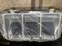
Real time question for the dentside aficionados…
My gauge cluster is very much mechanical sweep not idiot lights (18 pin in theory)
The trucks wiring harness is very clearly 14 pins (idiot lights)
The long story is that I do not want a factory cluster and am only considering it for the speedometer for the upcoming test drive. Will it cause any electrical gremlins if I do or do not plug it in? Immediately I think about headlights or turn signal function…..
OX1 by that mod to the valve, is there any function left? Honestly I’ve never analyzed one before, I’ll study that picture some more and absorb it.
Can’t edit my post above.
Need to clarify some info. Hydro cyl extended is full oil volume. Steering gear extended is reduced oil volume due to the ball/worm race. And vice versa. That’s how it’s configured.
Mine is installed the same way
Sort of, but your box is inboard which pairs up the high/high low/low oil volume
Here’s a diagram to back my explanation


 J/k, nice work
Yeah i get it. I first added hydro assist in 06 and didnt have any clue what i was doing, i just knew i needed itreptillikus is your assist 1.5” ? And I’m not grumpin on your setup, I had just never dumped all my squirrels nuts into text before

Good eye, sir!!! It crossed my mind once for style points but I kept spacing it. The bolt is incomplete in other regards too. I was boring and tapping the ends of all the bolts for safety caps but by the time I got to this one I had burned up all my drills and broken 1 tap. It’s probably permanent at this point because I want to drive this damn thing. Getting impatient.Where's the hatch marks so you knows its a LH bolt?


Thanks! It’s turning out how I imagined it so far. The bed was hitting the easy button for sure.Thanks for posting about the bed, I plan on going that route instead of working my current one when the time comes. This thing is coming together fast and looking good.
So much easier than wrastlin a couple a box wrenchsneed me an AN vice block that that....