What's new

1959 GMC 2 ton bus - 4x4 swap

Check with the manufacturer on your servo valve, in many cases the port marked "tank" has a limit of something like 300 PSI and is not intended to be used for power beyond (which would be what you're doing in this case).
Edit, looking up there plumbing diagram for a Sprint car, they show the tank line off of their power steering rack going directly to the tank and the additional valve to control the wing being before the steering, based on that unless they say differently I would bet that there is a pressure limit on their tank port: https://sweetmanufacturing.com/uploads/files/Sprint Steering Plumbing Diagram.PDF

Screenshot_20231111-070846-737.png


Additionally, you don't want your steering to be restricted if you're stomping on the brakes.
If there's only a pressure in and a return to tank out port your power assist/power steering will be reduced unless the out line is unobstructed.
If your hydro boost is downstream of the steering valve, when you are stomping on the brakes the fluid leaving the steering valve will not have any place to go until build enough pressure to overcome the resistance of the amount of force you're using from the power boost before you can steer.
Let's say you run a 1500 PSI pump, if your hydroboost is using enough flow to create 500 PSI of back pressure, that means you'll have 1000PSI worth of steering assist available, but to use it you'll have to overcome 500 PSI of back pressure.


Aaron Z

Thanks for the analysis here Aaron.

My Sweet servo is different; it's their "standard" size, but I think your analysis is correct. Sweet is extremely vague about all this stuff, though I sent them an email - hope they clarify.

This is what I have:

0unoNAP.png


This is from Woodward steering which, far as I can tell, has an identical product:

uFiF1RY.png

aZZWlp7.png


The three highlighted points being key to why I think you're correct on this and my plumbing needs changed... That last point also explains why some Sweet diagrams have a -8 return and some have a -6 return with no explanation given. Annoying. What got me confused was Sweet often pairing this servovalve with their "pressurized" tank.

Worst case scenario I just put my hydraulic "loads" in "parallel" rather than in "series" correct? Like this?

Czng5N7.png


Yellow "T's" being T fittings, and yellow circles being check valves (would those be necessary)?

If I do this, should I make the common feed and return lines a larger size (e.g. -8) before splitting off to each hydraulic load, or is it more important that only the return side is a larger size, so as to create a larger pressure differential?

WaterH Which unit is yours? My hydroboost unit (Bosch Hydromax from an IH 3800) definitely has a low pressure outlet; as it's just a barb with a hose clamp.
 
Thanks for the analysis here Aaron.

My Sweet servo is different; it's their "standard" size, but I think your analysis is correct. Sweet is extremely vague about all this stuff, though I sent them an email - hope they clarify.

This is what I have:

0unoNAP.png


This is from Woodward steering which, far as I can tell, has an identical product:

uFiF1RY.png

aZZWlp7.png


The three highlighted points being key to why I think you're correct on this and my plumbing needs changed... That last point also explains why some Sweet diagrams have a -8 return and some have a -6 return with no explanation given. Annoying. What got me confused was Sweet often pairing this servovalve with their "pressurized" tank.
Just went and looked at the hydroboost on our stock 2005 Yukon XL (for sale if you're looking for one :grinpimp:). That has a high pressure line from the power steering pump going to the hydroboost, then a high pressure line from the hydroboost to the steering box and a low pressure return to tank from the hydroboost and the steering box.
Worst case scenario I just put my hydraulic "loads" in "parallel" rather than in "series" correct? Like this?

Czng5N7.png


Yellow "T's" being T fittings, and yellow circles being check valves (would those be necessary)?

If I do this, should I make the common feed and return lines a larger size (e.g. -8) before splitting off to each hydraulic load, or is it more important that only the return side is a larger size, so as to create a larger pressure differential?

WaterH Which unit is yours? My hydroboost unit (Bosch Hydromax from an IH 3800) definitely has a low pressure outlet; as it's just a barb with a hose clamp.
Nope, can't do tees on the high pressure side, it's what they call an open center system, fluid constantly flows through the system at a volume that corresponds to engine RPM, if you put a t in it would just take the path of least resistance.
The high pressure lines all have to be in series one after the other, a low pressure return a tank can be teed because (as the screenshots you posted from the Woodward manual say) the energy has been exhausted because it's done all the work it's going to do.
Here is how the stock Chevy system is plumbed and how I would do it:
Screenshot_20231111-140428-727.png

Red line is high pressure output from the pump to the hydro boost
Yellow line is high pressure carry over or power beyond (depending on whose nemoclature you want to use), yellow will have however much flow is not needed by the hydroboost.
Green is low pressure return back to the tank, should be under 300-500 PSI (generally speaking)
Blue is suction from the tank to the pump.

If you aren't using the brakes or the steering, the entire system will be at a low pressure (generally under 500 PSI at least on our tractor that has a similar system and a pressure gauge where you can see it, it sits around 150-300 PSI when it's not doing anything depending on how warm it is), fluid will go from the pump via the red line to the hydroboost, onto the steering via the yellow line, back to the tank via the yellow line and return to the pump via the blue line.


If you step on the brakes, it will divert flow that came in on the red line to apply the brakes, and that fluid will return to the tank via the green line.
If you do not have the pedal down all the way you will not use all the fluid available from the pump, so the remaining fluid will continue on to the steering the yellow line.

When you steer fluid from the yellow line is sent to the cylinder (either the external cylinder or inside the rack) and fluid exiting the other side of the cylinder goes back to the tank via the green line.
If you're turning slowly and are not using all the flow available whatever flow you are not using returns to the tank via the green line.

With that system, if you're braking hard you will not be able to turn quite as fast, but you should have enough flow to still be able to turn and with the return to tank being separate from the flow on to the next device if you have the steering wheel up against the stops to one side it won't prevent you from braking.

Aaron Z
 
Just went and looked at the hydroboost on our stock 2005 Yukon XL (for sale if you're looking for one :grinpimp:). That has a high pressure line from the power steering pump going to the hydroboost, then a high pressure line from the hydroboost to the steering box and a low pressure return to tank from the hydroboost and the steering box.

Nope, can't do tees on the high pressure side, it's what they call an open center system, fluid constantly flows through the system at a volume that corresponds to engine RPM, if you put a t in it would just take the path of least resistance.
The high pressure lines all have to be in series one after the other, a low pressure return a tank can be teed because (as the screenshots you posted from the Woodward manual say) the energy has been exhausted because it's done all the work it's going to do.
Here is how the stock Chevy system is plumbed and how I would do it:
Screenshot_20231111-140428-727.png

Red line is high pressure output from the pump to the hydro boost
Yellow line is high pressure carry over or power beyond (depending on whose nemoclature you want to use), yellow will have however much flow is not needed by the hydroboost.
Green is low pressure return back to the tank, should be under 300-500 PSI (generally speaking)
Blue is suction from the tank to the pump.

If you aren't using the brakes or the steering, the entire system will be at a low pressure (generally under 500 PSI at least on our tractor that has a similar system and a pressure gauge where you can see it, it sits around 150-300 PSI when it's not doing anything depending on how warm it is), fluid will go from the pump via the red line to the hydroboost, onto the steering via the yellow line, back to the tank via the yellow line and return to the pump via the blue line.


If you step on the brakes, it will divert flow that came in on the red line to apply the brakes, and that fluid will return to the tank via the green line.
If you do not have the pedal down all the way you will not use all the fluid available from the pump, so the remaining fluid will continue on to the steering the yellow line.

When you steer fluid from the yellow line is sent to the cylinder (either the external cylinder or inside the rack) and fluid exiting the other side of the cylinder goes back to the tank via the green line.
If you're turning slowly and are not using all the flow available whatever flow you are not using returns to the tank via the green line.

With that system, if you're braking hard you will not be able to turn quite as fast, but you should have enough flow to still be able to turn and with the return to tank being separate from the flow on to the next device if you have the steering wheel up against the stops to one side it won't prevent you from braking.

Aaron Z

Well fuck, that's a pisser. Guess there's no way I can use the Sweet servo AND the Hydromax hydroboost I have together, eh? At least, not without a second pump?

In that case, swapping my Hydromax hydroboost for a GM hydroboost would work, right? We have some Chevy 4500 parts buses at work with these:

1699736883780.jpeg


which would mean I can plumb it like this, keeping the Sweet servo like so?

JreJCiG.png


I would be going down to a 1.50" MC... but on the other hand, that's the same size as used on the F-550 model year my front brakes came from.
 
Well fuck, that's a pisser. Guess there's no way I can use the Sweet servo AND the Hydromax hydroboost I have together, eh? At least, not without a second pump?
Not if it's plumbed like this one, you would need to change one of them as neither is setup to be second in line: http://1999southwind.com/DOWNLOAD/Bosch HydroMax Booster Manual.pdf
Screenshot_20231111-181332-398~2.png


In that case, swapping my Hydromax hydroboost for a GM hydroboost would work, right? We have some Chevy 4500 parts buses at work with these:

1699736883780.jpeg


which would mean I can plumb it like this, keeping the Sweet servo like so?

JreJCiG.png
As long as both can handle the full flow of the PS pump, that should work just fine.

I would be going down to a 1.50" MC... but on the other hand, that's the same size as used on the F-550 model year my front brakes came from.
Sounds like a plan to me, but I don't claim to know enough about MC sizing to have a good idea what will or won't work.

Aaron Z
 
Not if it's plumbed like this one, you would need to change one of them as neither is setup to be second in line: http://1999southwind.com/DOWNLOAD/Bosch HydroMax Booster Manual.pdf
Screenshot_20231111-181332-398~2.png


As long as both can handle the full flow of the PS pump, that should work just fine.


Sounds like a plan to me, but I don't claim to know enough about MC sizing to have a good idea what will or won't work.

Aaron Z

Looks like a 1.50" MC ideal for my caliper area, actually. Seems that other medium duty trucks with that size of MC have near-identical caliper piston area.

Thanks again for the help here. Probably saved me some major headaches, and this new hydroboost/MC combo seems a better size for my application. Got lucky today and was able to find one to rip off one of the parts buses we have.
 
Looks like a 1.50" MC ideal for my caliper area, actually. Seems that other medium duty trucks with that size of MC have near-identical caliper piston area.
Makes sense
Thanks again for the help here. Probably saved me some major headaches, and this new hydroboost/MC combo seems a better size for my application.
Glad I could help share some of the knowledge that has been shared with me over the years.
Got lucky today and was able to find one to rip off one of the parts buses we have.
Always good to find cheap/free parts that are just what you need...

Aaron Z
 
Firewall and doghouse is pretty much done. Finished up with the seam-sealer, rivets, rivnuts that wiring harness/hydraulic line P-clamps will attach to. Not the best photos, but you get the idea:

1700362791845.jpeg


This stuff works well, but it was a bitch and a half to peel the paper off...

1700362830761.jpeg


1700362908393.jpeg


1700362920955.jpeg


Will need to finish it up another day, but I'm happy that I got the entire doghouse done in one piece; no seams in there. Plan is to do a layer of aerogel blanket and then typical black automotive fabric on top, for the inside. Since I'll be living in this thing, lots of insulation is important.
 
Been cold as shit so have just been taking parts off the bus and working on them in my shop. Nothing worthy of pics; cleaning up some engine stuff, grabbing the final parts for the hydrosteer/hydroboost, etc. Got the wheel centers laser cut. Real happy with 'em! Two arrangements for the front:

Axle has a 77" WMS, this gives a 70.5" track width:

1701151214723.png


...and this gives a 74" track width:

1701151502632.jpeg


I much prefer how the wider track width wheel setup looks. It also matches the rear axle's track within 0.25" and is obviously a bit more stable. Importantly, there is no gap between the adapter plate and the wheel if I run it this way. With the narrower track width setup, dirt, snow, water etc. can get caught between the aluminum rim and the adapter plate in a 3/8" gap. Not sure if any of that makes sense from the pics. (Ignore the slight gap in the "wide track width" pic above - it won't be there normally, but I didn't want to bother driving the 18 studs out just for a photo)

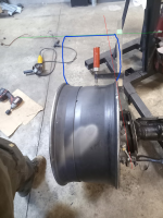
Main concerns with running that much offset/scrub angle with big 385/65R22.5" tires is the inner spindle bearing being in line vertically with the inner lip of the wheel; it's pretty far off from center. And yeah... a very large scrub.

How should I run it, you guys think? This is what In the pic below; +4" positive scrub radius. The wider setup adds nearly 2" to scrub radius and would put it right at the edge of the clamp. Those earthroamer trucks have a near-identical gross weight and tire size though, and their scrub radius is nearly identical to my "wide" option, so... Not sure what to do.

firefox_2023-11-28_00-20-56.png


Example of the earthroamer's scrub radius:
firefox_2023-11-28_00-15-23.png
 

Attachments

  • firefox_2023-11-28_00-20-56.png
    firefox_2023-11-28_00-20-56.png
    306.2 KB · Views: 7
I think the "wide" setting would be easier to keep clean where the old center was cut out. If I'm thinking of this right with the plate center on the outside it leaves a shelf on inside where gunk could build up overtime. I guess a big part will just come down to how it fits under the bus in the two different configurations.

Great work so far man, this thing is going to be cool.
 
I think it would depend on how powerful your steering ram is. I have terrible scrub on my HEMTT and can’t even notice with full hydro steering. In your case there will be some feedback.
 
I think the "wide" setting would be easier to keep clean where the old center was cut out. If I'm thinking of this right with the plate center on the outside it leaves a shelf on inside where gunk could build up overtime. I guess a big part will just come down to how it fits under the bus in the two different configurations.

Great work so far man, this thing is going to be cool.
Thanks man, I appreciate that.

I think you and WaterH are right about the scrub radius being the less important factor out of all the ones going on here. Stability is pretty important, the ram is pretty big at 2x11"... I think I'll do the wider arrangement for now.

Also thinking about running an intercooler. Power increase aside, will the cooler air charge help keep the engine operating temps down? I assume no if running hard, because denser charge = more fuel to keep the correct AFR, but I can see that it would help while cruising? Keep reading conflicting info on this, not sure what to believe.

The bus' original brass rad I intend to use has identical surface area to the rad that intercooled DTA360's came with, for what it's worth...
 
Got a lot of on-site welding done today. 12 patch panels all over the bus. Not often I get a chance to bring a generator out to the place:

1702186085921.jpeg


How it was before:

1702186104754.jpeg


1702186320775.jpeg


Previous owner cut a hole here and had what looked like the exhaust, routed through passenger footwell and up through the hood... lol

1702186534319.jpeg


A group 31 battery and 14kWh of lithium will go in a box here, recessed into the floor, insulated (or kept above freezing, at least).
 
Wheel centers painted up and bolted on...

1703735504662.jpeg


1703735527328.jpeg


Added a gasket to the interior so nothing leaks between the wheel and the new center plates (the center of the aluminum wheel steps down about 2mm).

1703735624493.jpeg


1703735642691.jpeg


POR15 for the rad support and VHT roll bar and chassis paint a try for the wheel centers. Seems pretty durable, and should be easy to touch up in the future with any black spray paint.
 
A larger scrub radius always feels weird to me in my experience. You're not gonna know for sure till you drive it, but you may want to try reconfiguring to the narrower setup if your steering feels heavy at low speeds. More scrub obvs causes the tire to walk more through turn radius than zero scrub, which makes it feel heavy imo.

Sorry if I missed the specifics, but these are the 22.5" size Hutchinsons? I breezed over the post when you got your mitts on them, but now I'm intrigued.

Yeah, shouldn't be too hard to reconfigure. The other question will be if the larger scrub radius causes the tires to hit the fenders/ bus body. Hopefully scrub will be alright though.

They are indeed 22.5" Hutchinsons. Not many out there, I'm only aware of 5 other wheels; 4 others apparently being on a 4x4 topkick in Montana, and 1 narrower version of the same wheel sold by Eastern Surplus: Goodyear G275 MSA 335/65R22.5 Tire Mounted on Unimount 18 Bolt Rim 100% Tread Tire HMMWV

Interesting story behind them, confirmed by Hutchinson themselves: All of these wheels were sold to AM General. I assume they would've been for the NXT360 or FTTS. The seller of the wheels - who owns a large scrapyard in Michigan - said his brother works for AM General, and after testing completed, they were allowed to take the wheels and a few other things which are nominally "civilian" off of the test vehicles, before destroying them at the seller's yard. I guess because anyone could order a small batch of these wheels through Hutchinson... at the cost of your firstborn child. :homer: Guy hung onto 8 of them for a few years, sold 4 a while ago, and canned the project they were intended for this year, so he sold the rest to me. They're stamped with August 2010 as the date of manufacture, DOT code, and a few different serial numbers. Found these on FB marketplace and couldn't believe my eyes lol.
VdPSjmu.jpg


Hauled them back to Canada with one very undersized uhaul... :grinpimp:
 
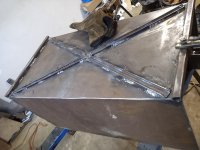
Finishing up the doghouse here:

1707025838144.jpeg


1707025850780.jpeg


Used the original data plates, (since stamped with the updated "data")...

1707025953374.jpeg


Bead rolling is pretty fun. :smokin:

1707026001794.jpeg


Made a shroud of the hydraulic steering servo. Would rather avoid hydraulic injection injuries to my nads heh...
 
1709784814441.jpeg


1709784694537.jpeg


Building a box for my 13kWh lithium batteries that'll be sunken into the floor in the bus, in order to save interior space while still having everything easily accessible and insulated. You can see where it'll go here:

1709784854021.jpeg


I may also use this pneumatic cylinder for fuel shutoff. Whipped up a little bracket and linkage for it:

1709784909680.jpeg


My thinking is that, since air is necessary for the transfer case range and 4WD selection, this will act as an interlock, preventing the bus from being driven when it shouldn't be (though you could just pull the fuel shutoff open/closed in an emergency).

1709785249067.jpeg


1709785491117.jpeg


Added a proper "housing" for the shifter boot, too. It'll raise it up 2.5" from the steel floorpan to account for the insulation and hardwood. Once the above things are installed, the bus will be fully sealed up from the elements... Finally. Pain in the ass having it far from where I live. Makes fabrication such a slow process; lots of measuring, fitting, measuring again, and making changes...
 

Attachments

  • 1709784590910.jpeg
    1709784590910.jpeg
    210.3 KB · Views: 7
So if there's no air and the solenoid closes, how are you going to start the engine?

I'll be living in this thing part-time, and will want onboard air for a variety of reasons; so I'll be using a 24V compressor that can run whenever, rather than an engine-driven unit. If that compressor failed, opening the dash valve, moving the solenoid by hand, then closing the valve, keeps it in position pretty well.

I also have an identical solenoid with spring-return, so I could use a burst of air pressure to shut fuel off, and spring pressure to keep fuel on. it would fail to "fuel on", rather than fail to its current state.

A bowden cable would be nice, but, there is little room to mount one without some very tight bends leading up to the dash. Suppose I could make a bellcrank or something though.
 
Good thinking ahead on the shift boot to floor spacing. I can't wait to see this thing on the axles and tires.
 
Good thinking ahead on the shift boot to floor spacing. I can't wait to see this thing on the axles and tires.


Thank you!

Wanted to keep the bus lower to the ground to make engine/firewall work easier, but now that's wrapping up, the front end will go in very soon. Just need to find a couple extra leaves for the front, re-make the passenger side spring plate (D60 one won't fit) and she'll be good to go.

The rear has been done for a while and could be slipped under as is. Half of me wants to just do that and get the thing on the road, but I know I'll want air ride or longer springs back there. It's also under-capacity currently: 52" x 2.5" springs at 4500lbs. Unlike today's school buses that use practically the same spring pack as their straight-truck brothers, my bus actually came sized for a load of 26 children... Great for them, not for my build. :flipoff2:My current plan is to add something like Kelderman's 2-stage air ride. Simple enough to build. Would let me keep the leaves, have air ride, but if a bag blew, I would have the old shackle hanger still mounted on the frame as "backup" if that makes sense.

View attachment 1710000210506.webp
I could get a Freightliner Airliner cutoff for cheap, but I'm not sure that's the right choice for a vehicle like this. 4-linking would be nice but I just don't have the time or money for that on top of what I already need to do. 63" motorhome leaf springs maybe; cheap, soft ride, good flex? Any other ideas?
 
Small update here, but one anyone playing around with biodiesel/WVO might find interesting:

Exposing biodiesel to copper, brass, zinc, will accelerate oxidation and alkyl esters in the fuel will create gelling/preciptates you don't want, or just outright cause brass/copper fitting to disintegrate if they sit in the fuel long enough. Nickel, however, is unaffected. Nickel is also dead-easy to plate at home:

1710909896428.png


Some white vinegar, table salt, and a strip of pure nickel from scamazon.com and you're in business. Make your nickel acetate plating solution by putting one half of the strip on each electrode until the solution turns green, then put the part of be plated on the negative, and a piece of nickel strip on the positive... let 'er sit for half an hour at 3V to 7V, and:

1710910275789.jpeg


Definitely doing more of this. it's way quicker, easier, and arguably tougher-wearing than paint for tiny parts like this. The plating solution will last forever as long as you don't contaminate it with oil, dirt, or confuse it with mountain dew... :grinpimp:

1710910422084.jpeg


Since the 13kWh "house battery" will be 24V, I decided to make things simpler and use two 12V starting batteries in series, with a 24V starter/alternator. Turns out the M35A2 starter bolts up just fine to my DT. Have since cleaned, painted, and mounted it:

1710910719828.jpeg
 
Good to see you plugging away at it man.

For your first attempts at plating you can also unravel guitar strings that have the "pure nickel " wrap on them :lmao:.
 
I wish my motorhome was 24V. It would make a lot of things better. 48V would be even better.
 
I wish my motorhome was 24V. It would make a lot of things better. 48V would be even better.
Far as switches and lights go, a lot of stuff is 12V/24V dual voltage... DC-DC buck converters are also cheap and easy to find nowadays. Might be worth seeing if you can do it. I like 24V because many boats and trucks, not to mention surplus NATO equipment, run on that voltage. RV appliances are usually dual voltage too. Makes it easy to find components for the vehicle side and the house side of things!

I've worked on a few 48V conversions on bus campers and such, and it really only seems to make sense if the bulk of your power is being used as AC through a massive 48V inverter. The biggest caveat is that you must use a DC-DC converter for charging off the alternator unless you can work an expensive Balmar or 48V mild hybrid BSG alternator into your system... good luck finding one though. With 12V or 24V you can just use a beefy off the shelf alternator that won't overheat (assuming your batteries are lithium) or use a smaller alternator with a wakespeed regulator.
 
Top Back Refresh