arse_sidewards
Contrary to everything
- Joined
- May 19, 2020
- Member Number
- 71
- Messages
- 7,838
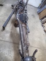
I really like this front axle build.
Follow along with the video below to see how to install our site as a web app on your home screen.
Note: This feature may not be available in some browsers.
Thanks!I really like this front axle build.
That's exactly why I went with the bottom truss; I need this axle to carry a lot of weight, more than I need it to have amazing ground clearance. I have 42" tall tires anyways. No threat of buckling with a truss acting in tension.Really cool stuff going on here. I like the bottom truss. I know people say it loses ground clearance, but I has the benefit of being in tension. The only thing I don’t like is the tie rod being low. just because the truss is in front doesn’t mean it’s protected. But if it’s the only way you could work it, it will have to do.
Any opinions on Mile Marker 459SS lockouts? On a tight budget and the Warn 62672 are too pricey when I take into account shipping + exchange + taxes up north here...
Thanks. I actually ended up getting the Warns in a trade - brand new ones!I have these hubs on a DD excursion. I have no complaints, they even come with a tool to help turn the dial. Any normal dana 60 lockout will work. A cheap junkyard option is the mid 90's TTB50 lockouts
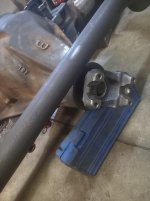
Agreed. I've sheared half the screws off lol. I plan on welding the bottom of the clamp together, while keeping the top open. I'll then weld two plates onto either side of the top, and add a couple 3/8 bolts to clamp it together.That clamp on ram mount looks really fancy, but I’m not sure I would trust it. Does it have any kind of key into the tie rod?
Sweet, I'll do that.Post them up to the CAD library (click on "Resources" in the top bar then look at the left sidebar).
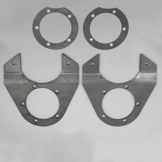
I like that you designed blank plates so anyone can make them fit any caliper by mocking it up and then welding on different tabs.
Does the D70 you have use the same bolt circle for the spindle as a D60?
For the calipers, I used 2005-2016 F-550/F-450 ones. (18-B8047B and 18-B4046B). New enough that there's good future parts availability I figure, and they're used on a few International chassis as well.What rotor and caliper did you use?
Aye, I use those calipers on a lot of rigs. Shipped some to shortbus4x4 to go on an Axletech 4K with brackets.For the calipers, I used 2005-2016 F-550/F-450 ones. (18-B8047B and 18-B4046B). New enough that there's good future parts availability I figure, and they're used on a few International chassis as well.
For the rotors, I used International 4400 ones. (680943R). They're also used on the majority of medium duty class 5 and up chassis; International CV/Chevy 4500, Ford F650, several motorhomes.
Thoughts over bent brackets instead of welded 3X?
With bent brackets, I think it'd be easier to ensure parallel planes between the spindle mount and the caliper mount... if you've got a brake capable of 3/8". I don't. But I will accept a donation for testing purposes.Aye, I use those calipers on a lot of rigs. Shipped some to shortbus4x4 to go on an Axletech 4K with brackets.
Thoughts over bent brackets instead of welded 3X?

I would assume he means this sort of thing:Pics of bent brackets?
I figured it was something like that. Looks clean and a little lighter. Might be able to make something with a bearing press and a torch, but I don’t see anything wrong with what you’re doing.I would assume he means this sort of thing:
These are from TMR, for the Ford D60.
Ford Dana 60 Front Disc Brake Brackets
CNC laser cut & formed from 3/8" high steel Utilizes '73 - '87 3/4 ton 4x4 front calipers (RC4072 & RC4071) and rotors (5014R) Sold as a pair (2 brackets) Fits 78-91 Ford King Pin Dana 60, single wheelca.tmrcustoms.com
Bet you could actually make these work if the center bore is around 4.880" - no idea what it is on a Ford D60 spindle - and you don't mind redrilling the 5 boltholes.
I figured it was something like that. Looks clean and a little lighter. Might be able to make something with a bearing press and a torch, but I don’t see anything wrong with what you’re doing.

Thanks man!NICE
Looking good man, only thing I would add is spend some time cleaning the seal mating surface. I've never had good luck with closed knuckle seals if there's any pitting.
Check with the manufacturer on your servo valve, in many cases the port marked "tank" has a limit of something like 300 PSI and is not intended to be used for power beyond (which would be what you're doing in this case).Anyone here familiar with Sweet servo valves? Am I correct that pressure leaving the valve is about the same as pressure entering it? Therefore the pressure leaving it is high enough to use for my hydroboost and the following would work, right?

- Blue rectangle is reservoir
- Blue circle is pump (4.5 GPM)
- Pink is 3/4" suction line
- Green is 3/8" pressure line
- Red is 1/2" return lin
 Largest to ever go on a Dana 70, far as I'm aware.