What's new

14 JKU M-380 "Kilroy"

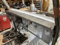
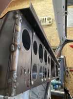
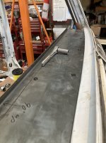
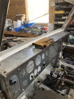
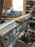
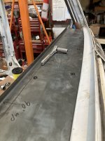
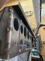
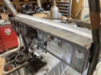
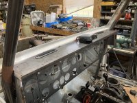
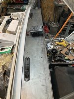
cool - my local metal supplier also has large metal-working equipment, and was able to brake a perfect 3/4" lip across the front of my dash cover panel, and it turned out great - just some edge work and it'll basically be done. Now there's tons of storage for any/all small gear, the radio, gloves, etc...and hey like 300 ducks - ha! (...no...)...

Y6u4Axy.jpg


GlkjEqB.jpg


wfAg3LR.jpg


KHVRNFL.jpg
 

Attachments

  • Y6u4Axy.jpg
    Y6u4Axy.jpg
    342.2 KB · Views: 4
  • GlkjEqB.jpg
    GlkjEqB.jpg
    133.3 KB · Views: 3
  • wfAg3LR.jpg
    wfAg3LR.jpg
    148.2 KB · Views: 3
  • KHVRNFL.jpg
    KHVRNFL.jpg
    193.2 KB · Views: 2
  • KHVRNFL.jpg
    KHVRNFL.jpg
    193.2 KB · Views: 4
  • wfAg3LR.jpg
    wfAg3LR.jpg
    148.2 KB · Views: 3
  • GlkjEqB.jpg
    GlkjEqB.jpg
    133.3 KB · Views: 3
  • Y6u4Axy.jpg
    Y6u4Axy.jpg
    342.2 KB · Views: 4
Last edited:
thanks - I'm really diggin' how it's turning out 👍

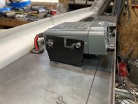
Couple more with the defroster vents and GMR-25 in place - I'll have a couple dividers to keep items from sliding around, and of course end caps, but this is pretty much it -

5jUCqNj.jpg


R8iLOPU.jpg


E87byf9.jpg


...and here's my wheel, along with a simple way to re-center it after some full-hydro 'drift' ;)

zFjagrQ.jpg


Fph6QbW.jpg
 

Attachments

  • 5jUCqNj.jpg
    5jUCqNj.jpg
    369 KB · Views: 5
  • R8iLOPU.jpg
    R8iLOPU.jpg
    192 KB · Views: 3
  • E87byf9.jpg
    E87byf9.jpg
    225 KB · Views: 3
Last edited:
orbital valve and column linkage - tried to get the o.v. as far away from the exhaust manifold as possible -

9WWl6jh.jpg


k9gaLAg.jpg
 
Got the glove box lid figured out, made another access port for the t-case linkage, pulled the body back off, and now am going front to back finishing everything I figured out over the last couple months, the first of which is taking the tranny to a local shop to be 're-sealed' - it's leaking many places and I'm going to have my tranny guy make those pesky problems go away once and for all.
Also, just before deciding to ditch the Dakota and build a Jeep, I started noticing a significant engine oil leak at the back of the block, and the good news is...as far as I can tell anyway...the oil leak was actually coming from the intake seal, and not the rear main...I think -

aDha5EB.jpg


DKVZHaO.jpg


HAXV9EQ.jpg


BO2Uh7S.jpg


AVBR9eA.jpg
 
k9galag-jpg.877598


When I mounted my orbital, I had the same thought to keep it away from the exhaust heat. My OCD kicked in and I didn't go quite as far forward as you did. My reasoning was if the serpentine belt let go, it wouldn't be lined up with the orbital hoses where it could possibly rip one off. Probably doesn't matter but, sometimes my brain works funny.
Keep up the good work, I'm digging what you're doing. That dash is awesome.:beer:
 
Ok - time to make stuff purty before final assembly 👍

Manifolds are sandblasted, and coated with POR-15 high-temp grey -
GgNZIxs.jpg


lyl96f1.jpg


4bhVmcq.jpg


StWkbuz.jpg


Frame/axle priming in work -
Aj1LfKi.jpg


D6K04ja.jpg
 
Last edited:
...got a lot of prep/priming/painting done (using good ole' rustoleum rusty metal primer and satin black paint), including the frame n hardware, gas tank cover, Barnes 3/16 shield, and front axle. Gas tank, front axle & suspension are bolted in -

SmXdcJ5.jpg


urchA9y.jpg


aRvD6M5.jpg


b73kEAP.jpg


jpZanvH.jpg


1PrAU7L.jpg


NmjB61K.jpg


XRfYJsg.jpg


wYYA6Qj.jpg


...think I read there needs to be just a smidge of toe-in, so I measured right at 3/16 -

iefMhHM.jpg


ztWn3Dx.jpg


pVmSFPA.jpg


was able to utilize the 4th (d-side) ram mount by welding half of it to the removable plate for diff cover access - worked great -

iHkP8YD.jpg


aTwaDEz.jpg


GD4efqt.jpg
 
360, 46rh, Atlas, and front shaft are in for good - rear 14b gets sprayed today.

Hoping to take it to Moab in October (at a 'minimum' capacity)...but if it doesn't make it I can still take the wife's big 08 JKU on 37s, and either way I'll just keep jammin' until it's ready.

CJW3Lnh.jpg
 
Last edited:
alright - after a month of measuring/marking/cutting/grinding/drilling/welding/sanding...I have both sections of the belly armor ready for paint. The main core section 'interfaces' with the Barnes gas tank shield and carries the shield to the other side, and completely protects the t-case, and trans cooler, which I'm mounting behind the t-case. It's all 3/16" steel, including 20 feet of 2" strap to reinforce the long panels against 'caving in'.

The engine/trans shield 'interfaces' with the core shield, all connecting up on the trans crossmember. The entire thing is completely 'smooth' - no bolt heads or edges to catch on stuff - just the drain holes...if those really count.

Next, the exhaust goes right along the d-side along with a corresponding heat shield. I'll be tacking the exhaust together for good once I have some other hardware in place. Ok - pics -

Core Shield -

PwHDfM4.jpg


8F37tEY.jpg


PKSNLQb.jpg


DEXK7rK.jpg


tcfMZQn.jpg


r7XDE3T.jpg


BoWQyFW.jpg


c2s2Ske.jpg


CRbuOq9.jpg


iAKJ9aI.jpg


9E9ARww.jpg


Engine/Trans shield (about 1" of gap between the shield and oil pan(s)) -

g4MRiZJ.jpg


k8EeMwW.jpg


ANQycpP.jpg


J77ifGT.jpg


9sEubdY.jpg


2ttRzHi.jpg


jqIWooe.jpg
 
How far below the bottom of the frame is the bottom of the skid?

Skids look fantastic:beer:

thanks 👍 - the whole flat bottom is about 2 inches below the bottom of the frame - it matches the Barnes gas tank shield as far as the overall depth, but it couldn't have been any higher as the bottom of the t-case is only about an inch above the shield.
 
...one thing I neglected to fully evaluate was how to drop the belly shield without inducing undue stress to the trans cooler lines, so I decided to mount the cooler and lines to the chassis and have them 'hover' above the shield, making it much easier and less messy when I have to pull the shield. The main bracket is welded to the big rear support bracket, which is removable/bolts to the crossmember, which makes the whole bracket removable, making it possible to pull/service the t-case, etc. Still some finish work to do, but here it all is -

cHnuYef.jpg


ujjV74G.jpg


UYYmjXA.jpg


line clamps attached to a plate welded to the trans mount bracket -

qiCO0xI.jpg
 
...ahhhh - love the smell of oil-based paint - always takes me back to my early days helping Dad and my bro-in-law paint the Jeep :) . Belly armor is primed and painted - should be ready to bolt it all up tomorrow -

2IYlCzq.jpg


p4jSIMW.jpg


2EUem7T.jpg


...and if I ever flop on my side this will be the view 😁

XyjrExn.jpg


ISSPRO fuel level float/sending unit installed - sanded the tank at the seal to smooth it out/help eliminate leaks - put Gasoila E-Seal on the threads and cranked the bolts tight into the collar, and it acts like studs and won't fall out if I ever need to service the float unit -

PDODMgF.jpg


WmG91ew.jpg


hc5ljEy.jpg


dWJ8E7K.jpg


CeUiT0A.jpg


Just an assembly tip - for those doing full hydro or any other application with a very shiny and perfect rod like shocks, etc., use a piece of leftover radiator or fuel line hose to protect the surface area from dirt, debris, and for sure welding slag -

XCsoIal.jpg


SJe6cQD.jpg


fBrwyFN.jpg


Lastly, here's an interesting view under the 2bbl throttle body -

ac3W8zd.jpg
 
...yep when I do the body I'm gonna use the brush/foam roller method for the Rustoleum rusty metal primer and then the USAF spec 'Strata' Blue (from Rapco)...but for the undercarriage it's just brush-on - not a fan of overspray when I can avoid it, even if it takes longer - besides I gots plenty of other things needing done in the meantime :grinpimp:.

That hardener - can it be used with oil-based paint?, and if I pour some of that in a quart can of paint will it dry it out if resealed or would I have to 'use it all' once poured in?
 
Last edited:
Yes it is for oil based acrylic such as rustolium. Once you mix hardener, you need to use it all. I just dump some into each roller tray worth of paint. It works well out of HVLP gun also.

If you want nice(r) finish without a gun, sand the base primer, and color sand rolled coat, then top with rattle can of the same.
 
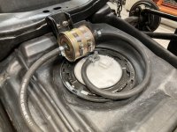
...high pressure fuel filter is mounted in place on a removable bracket allowing it to hover just above the sending unit while also being neatly under the trap door, which I will raise up just about half inch to give plenty of clearance, both easily accessible from the floor hatch - just remove the right-rear seat and the hatch is right 'there' -
Zp7dHEk.jpg


dmzFrIs.jpg


sq7xBlr.jpg


removable bracket to allow for removing the sending unit - works great -
xJvDSRR.jpg


tLHw1cU.jpg


removed a bit more from the floor -

LAZC19O.jpg


and will clearance this lower part just a bit more -
bNoI6Ax.jpg


Then mocked up the fuel lines and set the body on to check things out - pic from under the center console - sure is nice to be able to set the body on for fitment - noticed 'interference' between the projected fuel line route and outboard Atlas shift rod and cut yet another access port to enable me to maintain things that much easier -
LDW1Sx3.jpg


mUUAgZx.jpg


d2AKiET.jpg


Made a couple adjustments, and here's the layout. Both the feed and return are 5/16 EFI fuel hose from the tank to the throttle body, double wrapped first with DEI Vapor Block (pics) and then an outer heat shield from wherethehellever...
wbXTwTu.jpg


IpTo7nj.jpg


...and in the meantime...we have to have a new leach field put in...and they needed fill dirt...and we just happened to have a little project out back we wanted to do...so they helped us out by digging our giant hole...and we saved a bunch of $ on fill dirt - so now we have this to play in next to the rock pile :grinpimp:

u4Zk6LF.jpg


look close - there's a JKU on 37s in there...
lKuLoMb.png


ky2M6Xf.png
 
so...the factory gas tank sending unit has a smooth (not barbed) output port, which has a connector fitting with an internal o-ring...but when attached it just didn't seem to be very 'tight'...so I deleted the fitting and slipped the 5/16 hose directly over the port, which went on pretty tight, and then an EFI clamp to seal the deal - should work fine

U0By0rL.jpg


5xGQ5Rw.jpg


I'm confident this will hold up to 50-60 psi just fine...and simplifies 'everything' -
Fx3d6oG.jpg


with that done, attached all the fuel lines for good, and might even fill the tank all the way up and check the seals for the 'add-ons' - the float and return line - make sure they don't leak. Now is the time ...

aiaXj2L.jpg


5gC2TyE.jpg


vOf0nuE.jpg


fVrfxrk.jpg


mQC5kVL.jpg
 

Attachments

  • aiaXj2L.jpg
    aiaXj2L.jpg
    359.2 KB · Views: 2
...and that's why I post up my ideas to the congregation - there's always other ways. Ordered the fittings and I'll see how they work. Thanks for the link 👍
 
welcome! gives you an excuse to make some new bling fuel lines lol. your attention to detail is impressive
 
well thanks again - I try hard to have my junk look like decent fabrication and not fabricobble :flipoff2:
 
...one of the main reasons I post up the many steps of what I'm doing is to enable the opportunity for others to provide feedback on better ways to do a thing, a perfect example being the really slick aluminum fuel fitting that replaces (in this case) the OE plastic wrangler gas tank sending unit fitting the gas tank sending unit. Thanks again to slow600 for the link - I already have it installed. This is an aluminum, internal double o-ring fuel fitting which appears to be a specific replacement for the weak OE plastic fittings...and in this case appears to perfectly fit a '12 wrangler sending unit (which is 3/8) -

Evil Energy 3/8 - 6an EFI fuel fitting - https://www.amazon.com/dp/B07GB2R77C?ref=ppx_yo2ov_dt_b_fed_asin_title&th=1
Evil Energy 6an - 5/16 hose fitting - https://www.amazon.com/dp/B09494FV4N?ref=ppx_yo2ov_dt_b_fed_asin_title

As far as I can tell this fitting attaches to the plastic output tube perfectly - secures nice and tight to the stop lip -
myHIbL5.jpg


wVsaDQt.jpg


yUKameF.jpg


hWjsT9U.jpg


0CxMLrc.jpg


and with these upgraded fittings in place the fuel system is 'done'. I did slightly 'scar' the plastic output tube with my exacto knife trying to get the 5/16 rubber hose off (that didn't make me happy) so I had to lightly sand the edge down for the o-ring to seal up clean; I was planning to fill the tank completely to make sure the float and return line seals don't leak, and while I'm at it I'll energize the pump and pressurize the lines and check for leaks.
 
I assume the braid on the fuel lines is a heat insulator. Not sure you deal with extreme heat, but having the lines on top of the motor/trans will additionally heat the fuel. I don't see a way for it to cool (plastic tank, rubber lines all insulators). The return style system will always circulate fuel and pick up heat.

I would move lines as far away from any heat source as possible, but that is just me living in AZ.
 
...the only other way was to run the lines along the frame which would bring the lines very close to the manifold, and that was no good, so I went this route and put them as far away from the manifolds as possible. The system does circulate so there shouldn't be too much problem, and there's a lot of room for the heat to get out - should be ok.
 
Last edited:
I finally got the coils mounted. It took forever because I wanted upper and lower isolators for both the front and rear coils to the axles...but to my continued disbelief I could not find a source for a rear coil spring lower isolator...at least not for the Iron rock coils in my kit that rest flat on the 14b perch. The coils have a 2" i.d. at the base, and I needed a polyurethane bushing that would both fit the 2" hole just a bit tight and have an i.d. that would allow for a decently thick post to center on. After several rounds on Amazon of buy/return I finally found bushings that fit the bill perfectly...in the form of Kenworth motor mounts :) .

Get the mounts, pound out the sleeves, shave off the dome (that rests on the axle perch), cut about 1/2" off the length. Then a friend machined me a set of 1" x 1.5" steel posts with 1/2-13 internal thread, welded the posts to the perches...and the bushings fits my rear coils perfectly -
cpxT1KU.jpg


9LKtrSn.jpg


EQWQDJG.jpg


I used a wood rasp on my drill press to make a perfect chamfer to clear the welds -
IrYRN5Z.jpg


Fits the coil base perfectly -
VINAV0j.jpg


YbrRwZs.jpg


steel alignment posts -
cL8cXBF.jpg


Uck7mE8.jpg


After I bolted them in place I noticed the coils have a bit of 'bend' to them - due to the angle I have my 14b at to center the pinion joint - not really awesome, so I'm likely going to modify the coil base to zero out the bend...

NWshCd5.jpg


GGUFrN6.jpg


...the front coils were much simpler - a set of bushings from Energy Suspension did the trick with no mods, #9.6120G -
ICk0STj.jpg


Hlrua50.jpg


DY2is4U.jpg


x8qQHVx.jpg
 
Last edited:
Built a bracket to angle up the rear coil base mount - works great - squares up the coil nicely -
r9cNr9J.jpg


GWPCS4S.jpg


kjEc06V.jpg


before...
GGUFrN6.jpg


...after -
MyL7whA.jpg


And thanks to a big beefy Artec bracket the rear track bar is in -

uQ2fyXI.jpg


Front is in work, along with shock mount adjustments...
 
Last edited:
Top Back Refresh