What's new

WC53 Carryall Restomod - Cummins ISB170, Allison, ORI Struts

Depends on who you ask. I was provided a spec of "up to 12 degrees" from the Allison "Gurus" on 4BT swaps back when I started building this... well, thats all great but was obviously in a reading comprehension failure on the tech's part who I asked to look at the upfitters guide book.
The spec is max 12 degrees decline... and Max 5 degrees incline for continuous operation. The "guru" only saw the 12 degrees part I guess and never informed of the difference between decline and incline. So it can operate with the tail shaft facing up at a 12 degree incline, which evidently there are some operating in mining equipment, etc in that format, however the tailshaft down is max of 5 degrees. I was running at 7 degrees thinking I was perfectly safe. Oh well. I want to get this thing to 3 or 4 degrees if I can.
You actually want flat if you can for best operation, but up to 5 is acceptable.
 
I'd love that but that would literally mean back to square one, new firewall, new floor, etc etc in order to clear the oil pan to axle clearance issues.
Can you do a custom oil pan instead ?
 
Can you do a custom oil pan instead ?
Its already been notched for clearance for both the axle to stuff and for the steering to clear. The next thing in the way is the edge of the block. I think I can safely get little more drop of the engine and still have clearance if I deepen the notch and then add 1" of front ride height to help with some of it. It was always a little too low up front anyways.
 
Had the girlfriend use her small hands to help pull the radiator cover this morning. Yes, she is just sitting on the fender, truck does not care. I stand on them all the time.
I never did get the quick removal setup built and today reminded me of why I intended on doing that; there's just no room inside the cowl for hands or tools. I've got some ideas in mind for that.


Then I got to working on the transmission mount. I tried to salvage an old mount that I had put into the system. When I was chasing issues with the transmission and it was making a ton of noise and surging badly I added a torque arm to the engine and a third mount to the transmission. Well, once getting this last transmission installed, I realized that it was the bad original transmission and not the actual mount designs.

Anyways, this hanger was originally setup to support the GM style tail housing, which is the normal little rubber pad deal with two bolts / studs cast into the rubber mount. I didn't want to have to reinvent too much of the system so I just made a different adapter plate that bolts to the 4 bolt parking brake hub on the transmission. Theres a pilot ring that this thing sits in which is a nice detail. I was short on hardware so these are just test fit photos.

I just realized that I didn't get a photo of the completed 4 bolt tail housing flange before it got installed. Theres two extra gussets on the side that brace the bushing tabs to help transfer vertical load into the bolt and reduces some of the bending moment create by the slight eccentricity in the whole setup.

20220731_102103.jpg


20220731_102052.jpg


20220731_121453.jpg


20220731_183158.jpg


20220731_202958.jpg


20220731_203031.jpg
 
You gonna have to adjust the rear diff angle too?
 
You gonna have to adjust the rear diff angle too?
Nah, the T-case is divorced mount so I'll just have to adjust the shims / wedges I have under the mounts. The rear driveshaft is a CV shaft too and the T-case clocking won't really affect the pinion yoke.
 
The old Anchor 2589 front mounts are yanked out. Engine is reset at new mounting point and ready for me to build the new brackets. Got it down to 3.6 degrees which is plenty good I think. I ordered a set of low profile Hydraulic filled LORD mounts today. The brackets in the photo were from a torque arm thing I had built as I thought my surging was from that but it was from the converter locking and unlocking. Looks like I either need to find another upper radiator hose or cut and clock the steel neck. You can see it in the last picture to show how much the engine got dropped.
20220802_194020.jpg


20220802_174410.jpg


20220802_185747.jpg
 
Will you be altering the intercooler tubes also? I guess they can work there, but could clean them up a bit by shortening the vertical tubes.
 
Will you be altering the intercooler tubes also? I guess they can work there, but could clean them up a bit by shortening the vertical tubes.
I've got to tweak them some; unfortunately I can't shorten the down tubes much as the elbows have to clear the top of the radiator. I built the radiator as large as I could in order to maximize the cooling capacity since my original plans for this truck were to tow an airstream camper. Theres a pile of little details that have to be re-worked from dropping the engine.

What p/n are the LORD mounts you ordered?

Here is all the info on the LORD mounts. They were $145 shipped for the pair. I went with the 283P-400 based on the weight of the engine and the torque that the engine is rated to produce. 1600 lbs/in spring rate gives me about 1/4" of deflection at 420 flt lbs with the mounts at 8"ish off of crank centerline using the formulas provided in their tech literature. Engine weight is 720 lbs and the transmission is 325. Using the esimated COG F/R of the pair, the engine mounts will see about 325 lbs per mount so I am under their Max. I spoke with their tech folks on the phone and they agreed with my determination. I've had two folks on the book of faces tell me they opted not to use these because they think they might wear out prematurely by being too soft and really only for use with the R2.8. Dunno, guess I'll find out for myself.

Also, LORD is part of Parker, so they operate with territories. If you order them, here is the link to their vendors. I called the dealer in WI first just because I felt like they might be nicer than the Baltimore folks... They made me deal with Baltimore and turns out, their sales guy was painfully pleasant. Ordered these at 1030a on Tuesday and they delivered to my place in BFE between Cville and Richmond by 530p on Wednesday with standard UPS ground shipping.

Distributors for LORD - Parker Mounts

20220803_175809.jpg


Capture2.JPG


Capture.JPG
 
So if they do ware out quick (or are too stiff) you can change them out for the same design with a different durometer. That’s cool. I took a chance and got liquid filled mounts from a front wheel drive car. (Can’t remember right now) The guys on 4BT swaps recommended them. I’m really happy with them.
 
Very busy weekend, but unfortunately, not on this thing.
I did find about 2 hours yesterday evening to start getting the parts made for the new motor mounts. Figured I'd start on the easy open side first that doesn't have the area limited by a steering shaft, injection pump, and the fuel cooled ECM that is bolted to the engine; that side will be a challenge. That being said, I think that the passenger's side is easier, but this is still a challenge. I need to brake the one plate and then cut out gussets and such to brace the "wing" that will come off of the block plate. I tabbed some things so as to maintain some layout geometry. Test fitting the block plate on and it bolted right up perfectly using the only tolerance gained by a 12mm bolt through a 1/2" punched hole. The brackets here are all 1/4" thick A50 mild HRPO.

20220807_211513.jpg


20220807_211915.jpg
 
Did a touch of redesign after mocking bracket version 1 in and deciding that I do NOT want to have to remove an engine mount in order to remove the starter... as with my luck, the starter would decide to kick the bucket somewhere far from home where its unrealistic to have the truck towed and most Cummins dealers stock said starter. So, moved some things a little bit and ended up with a phallus shaped engine bracket. It should work just fine though. As it turns out, this was NOT the easy side. I started on the other side and the challenge there will be reaching under the steering shaft for the frame side mount. The engine is offset to the passenger's side, so keeping the same length arm on the engine for torque balance will require a longer frame side bracket anyways, so it does leave me room for the ol' reach-around.

Edit; The frame side bracket uses a 5/8" hole on the frame that goes through a slug and then it rests on top of the frame rail and will have two 3/8" bolts that are tapped through the top rail where there is a doubler plate inside the top frame lip. Didn't take pics of that but can when it comes out to get some paint. Weather looks like a good weekend for painting. Cooler with low humidity.

I am already concerned though that the mounts may be, in fact, a touch on the soft side and I might have to step up to the bigger weight capacity version afterall.

20220809_194830.jpg


20220809_194842.jpg


20220810_190231.jpg


20220809_213417.jpg
 
Last edited:
I am already concerned though that the mounts may be, in fact, a touch on the soft side and I might have to step up to the bigger weight capacity version afterall.
Givin the room you have, I really don’t see how you could make that much stronger. I don’t think thicker material will help much. Hopefully, it works fine. The way Murphy works, the engine mount will be fine and the frame mount will crack. Lol.
 
Givin the room you have, I really don’t see how you could make that much stronger. I don’t think thicker material will help much. Hopefully, it works fine. The way Murphy works, the engine mount will be fine and the frame mount will crack. Lol.
Oh, the bracketry all seems plenty stout for the loads, its the durometer of the LORD mount that I may have undershot.
 
Engine mount brackets are done. I missed the nice dry days for paint until end of this week. I had been using A50 HRPO for material and accidentally loaded a sheet of A36 HR mill scale crap onto the table, so that set of brackets got MIG welded. Ugly. Oh well.

20220815_195843.jpg


Started putting the air-shift system back together finally. Just using little 1/8" lines since its not moving much volume at all.

20220815_195919.jpg


Also - this thing takes forever to put fuel in. Part of it is because of this flat run that requires head from the neck. The other issue is that all I have for a vent is the roll over vent which is like an 1/8" hose barb and its on the far side of the tank. I am thinking of snaking a piece of 1/2" Aluminum tube down through this so that it just barely dips into the tank to help act as a vent tube. Think that will be enough to at least help some and reduce the back foaming? Yes, the hoses need to be that size to fit under the floor of the truck. In retrospect I would have done things a little different but that was 10 years ago and both my tooling and skills are much different.

20220815_195950.jpg
 
Yep, anything you can do to let the air escape a different path.
 
Ideally there'd be a big fat fill vent, 1/2" or 3/4" diameter, that connects to the fill spout right near the top, like these:
 
That looks bad for filling. Is there any chance of making your vent bigger? 1/8” hose barb is pretty bad. Is the material thick enough to drill it out and go bigger? The other issue I see is the neck down in the fill tube. I think it would be better to stay small all the way to the cap if you can’t go big all the way.
 
Ideally there'd be a big fat fill vent, 1/2" or 3/4" diameter, that connects to the fill spout right near the top, like these:
These.

cab_chassis_flatbed_service_truck_body_cm_truckbeds_dakota_bodies_knaphiede_custom_fuel_filler...png


I have done that to pre-runners with fuel cells. Otherwise they are damn near impossible to fill.

Getting tapered transitions for the fill hose to reduce turbulence would also be nice.
 
The filler neck is pretty much the way it is for aesthetics of the original body, granted the SS was to eventually be painted. I may install a JIC SS fitting into the neck and sneak an external tube up to it for venting as these normal filler neck is designed for. It may still only be a 1/2" tube but it is more than nothing. Sneak it off at a 45 degree angle towards the front fender side and it will hopefully blend in. I could even use some Copper tubing to give it that gasser / older method look. Need to order a 90 degree SS JIC fitting.

Started on the front driveshaft build finally. Been sitting on these parts now for quite some time. Cut the 3" tube close to length and then set it up on the lathe with the 4 jaw and the steady rest and squared off the ends. Tube length was 41.5" so working at the limits of my 48" bed Colchester.

Froze the yokes for a bit while I was cutting down the tube and then after deburring and cleaning was able to use a leather mallet to tap the yokes home into each end of the tube. I'll throw it back on the lathe between centers to check for runout on this setup before welding it. The tube itself did have a .020" belly on on side but only a .005" rise on the opposite so there is some sort of out of minor out or round / forming process / damage to it. I'm certainly not stressing it for a 3" seamless A513 tube front shaft in this thing. Ideally it won't see much high velocity anyways. Shaft OAL is 54.5"

20220816_180738.jpg


20220816_205138.jpg
 
Fuel vent solution... I had originally crafted a 3 port fuel return to the tank. It had tubes that extended down into the bottom of the tank to help reduce aeration. When the fuel system finally went together I was able to just use the one return from the FASS and then combined the 3 engine returns (CP3, FPRV, and Head Drain) into one system using some check valves. This left me with an unused port so I pulled the return head, removed the extra dipper tube and am using it for some sort of air return.

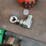
SS weld bungs are expensive, especially when you add in shipping, so I grabbed a 9/16"-18 SS nut, machined an O-ring seat in one side and then shouldered it down to create a slug. Using an ORB to JIC 90, some Brass fittings, and JIC flares on copper tubing to give it an aesthetic. Once the brass and copper gets some tarnish on it, it should look good. Pushlock hose to finish the connection for sake of things moving around some.

20220820_131751.jpg


20220820_132021.jpg


20220820_233435.jpg


20220823_204029.jpg

I started to do a sweeping bend to match the radius of the filler neck but it wasn't coming out smooth. If I end up hating it I can redo it.


I also got some work in on the floors and this is posted elsewhere too from me asking for thoughts on methods. I ended up grabbing a router bit with a bearing guide on it. Chucked it into the 1943 Bridgeport that was originally owned by the Navy in WW2, so appropriately... and then set the milling clamps with some tube spacers to act as guides and just hand fed the boards through... ie, Bridgeport router table.

The aluminum strips are then located, first hole drilled and spare drill bit inserted to the hold the strip from moving any and the remainder of the holes are drilled, strip removed and tapped for 10-32, and then the whole thing installed again with SS countersunk screws from the bottom of the plywood form board. The idea is that this is one big entity that can get installed or removed without having to take apart all of the boards. I ran out of screws because my vendor sent me one bag of 10-32s and another bag of weird sheetmetal screws that I didn't order instead of what I needed a few more of. So waiting on hardware. - McMaster rarely messes up too.

20220821_200737.jpg


20220822_185711.jpg


20220822_185627.jpg


20220822_133627.jpg
 

Attachments

  • 20220820_132434.jpg
    20220820_132434.jpg
    1.1 MB · Views: 8
WTH happened here? This setup has maybe 3k miles on it. Granted it was some thin wall tubing... thin enough actually that I was able to bead roll it into a barb ... so was that the issue here? Maybe a crack started from bead rolling the barb and then it eroded? This is looking from the bottom of the barb of the top radiator hose where the rubber hose goes on. Got a little too much air from the back side and corroded out? This was not expected. I guess I'll be turning a larger wall fitting on the lathe this time to replace it. I pulled it apart since I need to clock the fitting for the hose angle now. The aluminum parts all look fine and the coolant has only the slightest hint of rust color if any at all.

20220824_204537.jpg
 
Top Back Refresh