What's new

Steering Reservoir Tech (and Demo)

Are you using aluminum fittings? I have been scolded........
I have one aluminum barb fitting on the return. The rest are steel crimped or field serviceable. The return popped off because I had it zip tied to something else and when I hammered the gas up and obstacle, the motor torqued and popped it off. Cut the zip tie, and no other issues with it. On the ram, I think the hose was hitting the oil pan, and it was unscrewing the fitting, after the 90 was installed, it apparently no longer hits the pan.
 
Last edited:
Its time to mount the RD reservoir and at first I was thinking, WTF, how am I supposed to mount a 5 axis CNC aluminum chunk to the chassis with no bolt provisions. I know the PSC mount will fit the 3.5" but that thing is paper thin and uses a 10-32 screw threaded into aluminum. I was going to use two clamps on the old PSC res. but I sold those with the res. Otherwise I would have probably gone that route.
Now I am thinking a SS saddle with SS T bolt clamp?
What did you guys do?
Looks like they have their own 3.5" clamp: Reservoir Mounting Bracket 3.5
 
Hose clamps. Add some rubber in there somewhere if you're worried about shit scratching other shit. :flipoff2:

In this age of CNC shit it's a shame more shit doesn't come with a small groove on the back (like on the bottom of a machinist level) so it "naturally" holds itself straight on a rounded surface of almost any diameter.
 
The clamps on the website are PSC reservoir clamps. It's on my to do list to design new billet clamps for the 3.5" and 4" reservoirs but yes, the other popular option for both sizes that a lot of builders do is form a saddle that fits into the mounting groove with a t bolt hose clamp to secure it in place.
 
Its time to mount the RD reservoir and at first I was thinking, WTF, how am I supposed to mount a 5 axis CNC aluminum chunk to the chassis with no bolt provisions. I know the PSC mount will fit the 3.5" but that thing is paper thin and uses a 10-32 screw threaded into aluminum. I was going to use two clamps on the old PSC res. but I sold those with the res. Otherwise I would have probably gone that route.
Now I am thinking a SS saddle with SS T bolt clamp?
What did you guys do?
I took a piece of 3.5" ID exhaust tubing and made a saddle clamp out of that.
Worked out great.
 
Found a low pro filter head. The total height is near the same as the Howe filter res assembly. Hose rounting is not ideal but doable. SS schedule 10 pipe for the saddle. All -12 hoses suction and return, although the AN-12 is 5/8” ID.
IMG_5448.jpeg
 
Plumbed in the RD 3.5” reservoir and TC Pro.
I plan to plumb in a 3PSI regulator to keep constant pressure on the reservoir since I have on board air.
Plumbing in a remote filter to the reservoir was a PITA. It is difficult to imagine the chess game that occurred with the fittings and hoses. Finally I said it was good enough and went with the easiest routing, maybe not the best, but it is done. If I had started from scratch I probably would have mounted the reservoir in a different location than the filter, all though I have no idea where that would have been as there is no room left in the inn. The real trouble came from how long the suction line was. The reservoir was spun to make the suction hose as long as possible to give flex for engine torque. The trade off was how long the return from the filter to the reservoir was.
Eric from RD needs to figure out how to add a filter to the bottom of the reservoir. Simple task if you just replace the bottom res. cap with a filter cap, but incorporating the fluid path and or hoses and or tubes is another story.
IMG_5478.jpeg

IMG_5477.jpeg

IMG_5476.jpeg
 
Last edited:
All good feedback, thanks. I know it can be a challenge to plumb a separate filter and reservoir although there are some cases where it's an advantage since the reservoir can fit into a space without as much available height and the filter can be mounted anywhere else there is room in the chassis. For the most part, it has not typically been too much of an issue and every chassis is going to be different but you are giving me some ideas.

The bottom cap of the reservoir wouldn't be feasible with the current design because it is threaded into the body so there is no rotational position control of port fittings if I were to make that into a filter head, however, I am thinking about the possibility of a reservoir mounting assembly with integrated mount for a filter head below and a custom low profile connector to plumb from the filter outlet to reservoir inlet, this way I could do something with all standardized components. I'll give it some thought.
 
I too would be interested in a resi with an integrated filter (and pressure relief if possible)
 
A non spin on oil filter would also be nice.
Something like a shock reservoir with a cartridge filter. Could also have cooling fin exterior.

Or a bottom mount spin on filter with a sandwich plate that can spin 360° for clocking hoses.
View attachment IMG_5493.webp
 
Last edited:
A non spin on oil filter would also be nice.

You could stick a cartridge filter in the bottom of a cylindrical reservoir and just have a plunger of sorts on the cap to keep it down. Just vary the length of the cylinder and the plunger for different reservoir capacities. Obviously you'd need a cap about the same diameter as the whole reservoir.
 
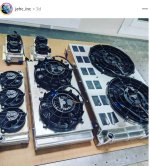
This is a older sketch that I have been working off of. You will see why Eric is suggesting a separate reservoir. (Cooling) And the reservoir can be below the pump (At least with the RDT - Trophy Truck Pump.) In the case of the high end Ultra 4 4400/TT racers the cooler is a fan cooled/steering only radiator. Typical cooling radiators (5-6 ) add up to about $10k and draw up to 240Amps. You may also notice a one way valve that is being tested to prevent pressure spikes back to the pump when a wheel/tire hits something and wants to kick sideways... and hydrolickly back against the ram/rack/orbital/pump. That became more prevalent with portals and the extra 4" lever/breaker bar/torque arm. (Blowing seals out of the pumps and etc) The pumps got the blame in the beginning...which have now been upgraded with newly designed seals plus the one-way and pressure relief. But sometimes the pressure spike happens so fast that sh__ still happens. Eric (RD) has been moving mountains for all of us. Try not to be a budget buyer but Eric will be the first to say that you look OK without replacing a whole system. Gaining experience daily. (Radiators: Water. Transmission. Oil. Steering. xfer...and maybe a diff)
RadialDynamicsPlumbing5.24.jpg
 

Attachments

  • Cooling packagesTrophyTruck.jpg
    Cooling packagesTrophyTruck.jpg
    101.1 KB · Views: 3
Last edited:
The vortex design is unable to accept an internal filter element since it is essentially splitting the flow into two paths, one for more aerated oil and one for less aerated oil. Therefore the filter needs to be outside of the tank itself but either locating it below with a low profile way to plumb from the filter to the necessary reservoir inlet location, or possibly integrating an internal cartridge into our inline coolers is all possible.

I wouldn't plan on trying to integrate a pressure relief valve into a reservoir assembly since one of the main benefits of doing a remote pressure relief and the whole idea behind the combo filter/PRV is that you can pass the PRV return oil, which is the hottest in the system, through a cooler before it makes its way back to the reservoir. This is one of the ways that we have been able to achieve very significant temp reductions in some of the Ultra4 and TT applications, in addition to the use of flow regulated pumps.
 
Eric, do we have an idea of how much hydraulic feedback we can be getting from a tire/wheel hitting a rock, etc. I heard that Ford monitored everything when designing the Bronco and during trips to JV for testing. All I would know to go by would be "good" hoses bursting.

LOL. I was just thinking that "cavitation in the lines" would give some compress-ability and maybe why the reservoir and other clear thinking is changing the game somewhat. We talked about an accumulator not being a good answer but?? The builders seem to be beefing up what they have, and appreciate a TT pump that will survive more than just one race.
 
I don't know what data Ford collected but I normally expect that peak pressure spikes will be 2 to 3 times relief pressure. These spikes are only 2 to 10 msec so most data logging systems generally aren't sampling at a high enough frequency to see them. Cavitation bubbles or dissolved air that has come out of solution that doesn't collapsed back into liquid phase by the time they leave the pump will definitely contribute to a spongy feel.

I'm still not 100% about accumulators that some of the TT builders have been playing with though. There is some merit to the shock absorption but at the same time, the volume change during the pressure rise is taking oil flow away from the steering response and with feedback in the steering wheel still being one of the top concerns, I believe that every bit of flow availability is needed. My thought is that a non-volume changing cushion such as a double relief valve, aka "shock valve" is a more suitable answer. I have been working with teams trying both methods but need to collect higher quality data before I can really draw solid conclusions.
 
There is some merit to the shock absorption but at the same time, the volume change during the pressure rise is taking oil flow away from the steering response and with feedback in the steering wheel still being one of the top concerns, I believe that every bit of flow availability is needed. My thought is that a non-volume changing cushion such as a double relief valve, aka "shock valve" is a more suitable answer. I have been working with teams trying both methods but need to collect higher quality data before I can really draw solid conclusions.
A cross port relief is going to burn up energy like a shock. An accumulator is only going to spread that energy over time like a spring.
A cross port relief is going to effect steering feedback during the impact. The driver will then react to recover the lost oil, if needed. An accumulator is going to effect feedback both during impact and recovery whether needed or not. An accumulator in theory is faster than a driver depending on if the recovery is needed.
Not sure what both combined look like. Basically a coilover suspension for the steering.
 
The other factor to consider is whether the system is fully hydraulic or still mechanically coupled. With monster trucks and other high impact full hydro applications, throw a cross port relief between the orbital and ram, set to 1.5X main relief pressure, and call it a day. Tried and true, and if it drifts a few degrees when you take a hard landing, it's typically not a big deal.

With IFS cars using a rack and pinion, you can't have deflection of the steering rack to absorb impact without also kicking that back through the steering wheel regardless of how the hydraulics are cushioned. The more I work with the TT community, the feedback I get is that they prefer steering boxes over racks because the steering wheel has less kickback and what I want to take a closer look at is whether this has more to do with friction between the leadscrew and piston or if it is strictly because the sector shaft is deflecting like a spring to take some of that shock load. I have a feeling that sector shaft deflection has a lot to do with it because a number of teams still struggle with bent sector shafts on a regular basis. Also supporting that idea is that we have seen reduced sector shaft issues with the RDT pump which produces roughly half the neutral load system pressure at high RPM versus the non-valved TT pumps and I believe that this helps maintain lower pressure spikes when a given pressure differential is demanded across the piston.

Thinking about the dynamics of a steering box/assist ram or a rack and pinion with either cross port relief or accumulator introduces so many variables to the impact response of a steering system that it can be difficult to wrap your head around. I don't have all the answers yet, but neither does anybody else. We are at least making progress in the right direction though.
 
Very cool stuff. Putting my learning cap on -

In your general observations between racks and steering boxes, besides the mechanical differences are they similar hydraulically, like running similar (remote?) servos? Do they run check valves like OEM boxes?

Interesting thoughts on the springy nature of sector shafts when running on the ragged edge, I could visualize that having an impact on feedback through the wheel too.

Stock steering hydraulics are open center right, so the fluid can pass freely through the servo until the torsion bar is twisted, the free return path is closed and the fluid is forced through the alternate path to provide assistance? I've thought about the concept of hydraulic accumulators in a steering system before, but couldn't wrap my head around how to have it fill/pressurize on an open center system. Are there closed center servos that could work in conjunction with an external pressure relief to give the fluid a return path when assist isn't demanded?
 
Ultimately you are applying similar amounts of hydraulic horsepower to the tie rods, so in that sense, yes they are similar. Of course, rack and pinions at that level are pretty much all remote servo valves, steering boxes are more often internal but the remote servos use the same guts as what you will find inside a saginaw steering box.

The servos are all open center meaning P-T-L-R are all open to each other in neutral. With a fixed displacement pump, a closed center system would not make sense without setting up a load sense priority valve but then you are adding delay to the system response. Not to mention that outside of full hydro orbitals, you aren't going to find a load sensing steering box or servo valve. The accumulators we are talking about here are relatively small volume, actually repurposed shock reservoirs, tee'd into the high pressure side of the system between the pump and servo so during an impact event, the accumulator compresses the gas charge during hydraulic pressure rise which should theoretically reduce the peak pressure spike.
 
This brings back memories of Rantz and the 4500 steering.
What was going on was the cylinder working VS the box piston working. The box piston could not handle the same load and flow rates as the cylinder so solution was to move the load to the cylinder and move the servo to a remote location to control the cylinder.
I’m guessing it’s not about box gear vs rack gear. It’s about flow, restriction, and pressure spikes.
It looks like steering is entering the realm of shock tuning.
 
Ultimately you are applying similar amounts of hydraulic horsepower to the tie rods, so in that sense, yes they are similar. Of course, rack and pinions at that level are pretty much all remote servo valves, steering boxes are more often internal but the remote servos use the same guts as what you will find inside a saginaw steering box.

The servos are all open center meaning P-T-L-R are all open to each other in neutral. With a fixed displacement pump, a closed center system would not make sense without setting up a load sense priority valve but then you are adding delay to the system response. Not to mention that outside of full hydro orbitals, you aren't going to find a load sensing steering box or servo valve. The accumulators we are talking about here are relatively small volume, actually repurposed shock reservoirs, tee'd into the high pressure side of the system between the pump and servo so during an impact event, the accumulator compresses the gas charge during hydraulic pressure rise which should theoretically reduce the peak pressure spike.

Makes sense on the rack vs steering box in the grand scheme, I was mostly just wondering what other variables (beyond the sector shaft) there may be between the two systems that make the steering box be more comfortable in regards to feedback. But it sounds like there aren't significant differences in the servos, at least not drastic ones.

Thanks for clarifying on the accumulator also. My mind was focused on the idea that the accumulator was charged when the pump was spinning, then discharged into the system as the servo ports opened (while still having room left to accumulate a bit more volume in the event of a spike). But it sounds like you're expecting it to stay essentially discharged until any pressure (or spike) is built in the high pressure line because of the open center meaning minimal pressure in the line until requested. Which seems like it would still help with spikes, but cause delay in the pressure rise in the high pressure line as it absorbs some volume of fluid? Hmm


Edit with another thought - were you thinking of charging the accumulator to like 1000-1200 PSI while empty? So it essentially never takes up fluid until one of those extreme events?
 
Last edited:
This brings back memories of Rantz and the 4500 steering.
What was going on was the cylinder working VS the box piston working. The box piston could not handle the same load and flow rates as the cylinder so solution was to move the load to the cylinder and move the servo to a remote location to control the cylinder.
I’m guessing it’s not about box gear vs rack gear. It’s about flow, restriction, and pressure spikes.
It looks like steering is entering the realm of shock tuning.
Very much so. And yeah, I fully get the restrictions in the box itself causing the power piston to fight the assist cylinder which is one part of the equation. But I do still think that the opportunity for deflection in a steering box is another major contributing factor to the feedback I am getting from drivers which makes sense when you consider the deflection that is bound to occur during a hard impact. The rack is that much more mechanically efficient than the box with less opportunity to absorb the load before transmitting it back up the steering column.
 
Very much so. And yeah, I fully get the restrictions in the box itself causing the power piston to fight the assist cylinder which is one part of the equation. But I do still think that the opportunity for deflection in a steering box is another major contributing factor to the feedback I am getting from drivers which makes sense when you consider the deflection that is bound to occur during a hard impact. The rack is that much more mechanically efficient than the box with less opportunity to absorb the load before transmitting it back up the steering column.
I wouldn’t be surprised if the box is flexing more than the gears opening the mesh and flexing as a spring.
 
Top Back Refresh