Project_Heepster
Well-known member
- Joined
- Feb 24, 2021
- Member Number
- 3543
- Messages
- 51
Just started this build a few months ago. Figured I'd start up a build thread now that there's a real place to put it again.
Project Heepster is my '67 Jeepster Commando build with a goal of building mainly off budget junkyard parts (hence, the "heep"ster name). This is my first major top to bottom build, so essentially I have no idea what I'm doing just learning along the way. Still have my XJ on 37's to run trails while this thing takes up all the garage space.
Here's a rundown of everything I'm planning to put into the project:
1967 Jeepster Commando Body
Stretched Jeep TJ frame (stock+14")
5.3L Lm7 (or possibly 6.0L if I can find a good deal, havent bought an engine yet).
4l60/4l65
NP241C
99-04 Ford Dana 60 Front
Ford Dana 70 Rear
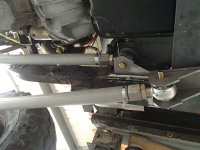
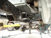
3 Link front
4 Link Rear (both on coilovers, we'll see what size I end up being able to fit)
40" DOT tires of some sort, want this thing to be streetable somewhat at least.
Here's some pictures of what it looked like when I bought it back towards the end of 2020. Bought it part way through someone else's project. Mostly for the tub since it was in reasonably good condition for a 50+ year old jeep. Didn't come with an engine and I sold off the TH350 that came in it, because 4 speed.
Stage 1 was getting a frame and suspension to make a roller to swap the body on to, which I'll put details into my next post.


Project Heepster is my '67 Jeepster Commando build with a goal of building mainly off budget junkyard parts (hence, the "heep"ster name). This is my first major top to bottom build, so essentially I have no idea what I'm doing just learning along the way. Still have my XJ on 37's to run trails while this thing takes up all the garage space.
Here's a rundown of everything I'm planning to put into the project:
1967 Jeepster Commando Body
Stretched Jeep TJ frame (stock+14")
5.3L Lm7 (or possibly 6.0L if I can find a good deal, havent bought an engine yet).
4l60/4l65
NP241C
99-04 Ford Dana 60 Front
Ford Dana 70 Rear
3 Link front
4 Link Rear (both on coilovers, we'll see what size I end up being able to fit)
40" DOT tires of some sort, want this thing to be streetable somewhat at least.
Here's some pictures of what it looked like when I bought it back towards the end of 2020. Bought it part way through someone else's project. Mostly for the tub since it was in reasonably good condition for a 50+ year old jeep. Didn't come with an engine and I sold off the TH350 that came in it, because 4 speed.
Stage 1 was getting a frame and suspension to make a roller to swap the body on to, which I'll put details into my next post.