What's new

CC Build: Porsche 996 to LS1 Conversion

Not sure because i have always had the gt3 lca that can be shimmed. I think 1.5-2* in front and similar in the back. U may need high camber upper mounts in front to get more. U can get affordable adjustable dog bone uppers in the rear that can get u more. I run 4* front and 3.1* rear

Caster in front is non-adjustable unless u get pucks for the lca but i should be in range or close enough.

No eccentrics in the front so nothing to lock out and the rear has lca and toe bar eccentric but they only offer a lock out kit for the toe bar and u would have to get adjustables. U may need the adjustable toe bars anyways depending on ride height.

The front sway links bolt to the upright so they should be fine and the ohlins should come with a bolt in bracket in back so u should be good there too. This all depends on ride height.

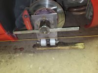
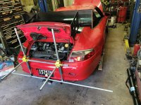
Easiest thing u can do is make some cheap hub stands to make alignments easier. I also have a set of string fixtrures that hook onto the car.
 

Attachments

  • 20230902_130548.jpg
    20230902_130548.jpg
    4.1 MB · Views: 54
  • 20230527_220002.jpg
    20230527_220002.jpg
    3.3 MB · Views: 54
Not sure because i have always had the gt3 lca that can be shimmed. I think 1.5-2* in front and similar in the back. U may need high camber upper mounts in front to get more. U can get affordable adjustable dog bone uppers in the rear that can get u more. I run 4* front and 3.1* rear

Caster in front is non-adjustable unless u get pucks for the lca but i should be in range or close enough.

No eccentrics in the front so nothing to lock out and the rear has lca and toe bar eccentric but they only offer a lock out kit for the toe bar and u would have to get adjustables. U may need the adjustable toe bars anyways depending on ride height.

The front sway links bolt to the upright so they should be fine and the ohlins should come with a bolt in bracket in back so u should be good there too. This all depends on ride height.

Easiest thing u can do is make some cheap hub stands to make alignments easier. I also have a set of string fixtrures that hook onto the car.
Tweaked my knee snowboarding and pretending I'm still 20. Been out of the shop for about a week but hobbling around again.

Got it, thank you. I remember going through your build thread and the GT3 conversion was very fun and informative, I learned quite a bit. I was researching the 996 suspension upgrades since I've been out of the shop and compared the gt3 lower arms (adjustable) to buying adjustable upper arms (dog bones). For my purposes, I think the upper arms are a better way to go. I need to get under the car again and make a plan based on worn components and fitment and track goals. After talking with quite a few fellow 996 track enthusiasts and P car shops, the upper arms and Ohlins are the best bang for my buck right now.

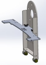
I also looked at designing my own alignment hub stands and it's not as cheap as I'd like, but stll considerable cost savings. It's about $650 for me to make a set, given I don't have my plasma CNC anymore and I'd be ordering hardware from McMaster. This DIY kit, however, is actually a good design and a pretty good deal from what I can see for about $850 all in:

I'll probably wait to make these until I'm tired of paying for alignments at the local shops. I'm going to attempt to negotiate an annual fee since I'll want to change alignment a few times a year based on street or track use. Unless I get lazy....which is very possible....and I decide to use a street setup on the track and avoid alignment changes altogether. Hah!

Anyway here's my design, a mix of others I saw. I'd probably make the bolt pattern plate a separate piece so I can swap it out for other vehicles easily. The bearings have a static load rating of 530 lbs each, there's 4 on each stand, so max load is 2120 lbs for each stand, 8480 lbs for total vehicle weight. Rolling load is quite a bit higher. I'll probably run these through FEA to see if they could actually withstand those loads, but for my little 3000 lb Porsche 911, these should work fine. Stand itself is 1/4" steel, laser cut and CNC bent, and the alignment plate itself is 3/16" aluminum for ease of use and storage. Alignment plate also has slots for tape measure, string cutouts, degree markings laser etched, and could be anodized for some bling.

If anyone is interested in a pair or set, let me know and I'd do a group buy and maybe we can bring down the cost. No profits, just straight cost for everything.

iso1.jpg


iso3.jpg


top1.jpg


iso4.jpg


I've also been pondering how I can add a X or H pipe to the exhaust. I think an X pipe is out of the question due to space constraints. I'm sure I could do it, and even started it in CAD again, but an H pipe is much easier. I was considering a pipe across the back, with 2 more v band clamps. This should be pretty quick, and if I screw it up, it should be a quick fix. What's the thoughts on this? I've researched quite a bit, and looked through as many other 180 header builds as I could find and most experiment with X pipes and keep them, some don't.

Curious as to everyone's thoughts and experiences on H and X pipes. H pipes typically offer more lower end grunt noises and X pipes offer more high end zings. Since my setup is already somewhat high pitched and sounds like two 4 cylinders, I think an H pipe would give it a more robust tone with a more exotic sound that I've been chasing.

996 180 with H pipe.jpeg


Current sound:


More expected sound with X pipe


H pipe vs X pipe video that really highlights the differences
 

Attachments

  • iso2.jpg
    iso2.jpg
    46.4 KB · Views: 8
My only suggestion is u bolt in a piece of steel milled flat to the hub bolt surface to place a magnetic camber gauge. A tenth of a degree counts on these cars.

I like your measuring plates...might be interested in a set.
 
man, i forgot all about this build. great to see it coming together. i need to get back into my 911/vr6 build. its got a bit of dust on it. man getting exhaust to fit your setup looks like a real mind crunch.
 
Since my setup is already somewhat high pitched and sounds like two 4 cylinders, I think an H pipe would give it a more robust tone with a more exotic sound that I've been chasing.
Do it!
copyofrockon-gif.627991


IMHO, the H-pipe will move the exhaust note in a good direction; an x-pipe would make it sound spastic :laughing:
 
Last edited:
No experience with it, but I don't think an H pipe will give you the sound you're looking for, however, I would like to hear what an H pipe there would sound like.

Is there enough room to stack two pipes over/under where you have the H pipe drawn? Be a PITA but, if you could Y directly off your header, one side of the Y goes to the muffler like now, the other side of the Y crosses over to a Y into the other muffler. Clear as mud? I don't think it'd give the same sound as a regular X pipe setup would since it wouldn't be equal pulse spacing. But, it'd be interesting.
 
My only suggestion is u bolt in a piece of steel milled flat to the hub bolt surface to place a magnetic camber gauge. A tenth of a degree counts on these cars.

I like your measuring plates...might be interested in a set.

Noted, I'll take a look at how to add that. If/when I make these, I'll send you a PM!

Man you guys are cheapskates. :lmao:

Contact my buddy and he will sell you arguably the best setup system used in the paddock at the moment

Twas a mere $38k for the one I used last week. Yup. $38 thousand.

Setup Wizard systems. Bring your credit report.

Too lazy - unless that thing does it for me, with tires on ground, it needs improvement. :laughing:

man, i forgot all about this build. great to see it coming together. i need to get back into my 911/vr6 build. its got a bit of dust on it. man getting exhaust to fit your setup looks like a real mind crunch.

Thank you! I'd like to see that 911 vr6 build! That must be a nice small package. Lots of room for nifty exhaust there. Yeah...if I were to do this again, I'd 3D scan the engine bay and start fresh. It's packed, which might suck for when I start racing, but the sound is worth it IMO.

Do it!
copyofrockon-gif.627991


IMHO, the H-pipe will move the exhaust note in a good direction; an x-pipe would make it sound spastic :laughing:

Thanks!! I'm planning to buy the toob and v-bands after I draft up a small curve for each side to make it a bit better of a transition, so it's a H/X pipe hybrid. I'll post pics of the CAD when I'm done.

No experience with it, but I don't think an H pipe will give you the sound you're looking for, however, I would like to hear what an H pipe there would sound like.

Is there enough room to stack two pipes over/under where you have the H pipe drawn? Be a PITA but, if you could Y directly off your header, one side of the Y goes to the muffler like now, the other side of the Y crosses over to a Y into the other muffler. Clear as mud? I don't think it'd give the same sound as a regular X pipe setup would since it wouldn't be equal pulse spacing. But, it'd be interesting.

I hear you and this was my first thought. Unfortunately, not enough room from my measurements to bring in an actual X pipe. I think the next best thing is what I described above, with a connection tube (H pipe) but with bent ends so it transitions smoothly out of the collector to each side.
 
Epic build!

Thank you!

Love the build.

I’d be highly tempted to try the H.

Thank you! I actually remember how you got your screen name...had a ton of the Maxx trucks back in the day and still want to build a SuperMaxx with UE parts. I read your original article (on paper!) from RC Car Action back in the day.

I'll be doing the H pipe for sure...I have to know how it'll sound or it'll bug me forever. :laughing:
 
Finally had some time in the shop amidst my own injuries and caretaking others. Half of the main car structure is ready for wrap - hood, pass fender, pass door, pass quarter panel, and roof - are all sanded, smoothed, and checked for gouges. I think I could just paint the car at this point, but the main drawback being the bumpers aren't exactly easy to paint, especially for a beginner with paint and body like me. For now, onward with the wrap and prep.

I need to either A) find a shop to attempt to repair the front bumper or B) try to repair it myself. The creases worry me a bit more than the punctures. I might just get YouTube certified on plastic welding and DIY.

I'm hoping to finish the rest of the main body panels tomorrow and possibly tear down and prep the deck lid. I need to do some minor trimming behind the deck lid outer panel so I can access the nuts that hold the body pin buttons and clean up the rough cuts with a flap wheel. Once that's done I'll paint the edges so they're not bare.

I took some bondo to the hood to fill in the very slight dent leftover from PDR. I didn't have to do this for the pass fender, thankfully. After a few rounds of sanding, and some primer to cover any exposed metal, I think the main dent and paint repair is done, at least for this side of the car. Drivers door looks terrible...hopefully they're just superficial scratches into the black paint and not into the green underneath.

Looks like crap but it's actually smooth and should take the wrap well. Anyway, here's photos of the current status of the car.

IMG_0425.JPEG
IMG_0429.JPEG


Don't worry, I smoothed it out after this. :homer:

As for the exhaust, I want to try to get that done while I continue work on the body. I designed what I wanted, and will be placing an order with Ace Race Parts since they're "local"-ish and I've stopped into their warehouse in the past.

Before anyone asks why 2 bend joints instead of 1 in the middle - each only gives 0.6 degrees of movement...not a lot. Aligning all these parts each time is going to be a pain without some tolerance built into the system, plus I want double the amount of available movement during heat cycling.

I give you the 180 degree H pipe :emb:

H pipe with flexes1.jpg
H pipe with flexes2.jpg
H pipe with flexes3.jpg
 
Another productive day in the shop. Exhaust parts are ordered, but I realized I need to do something about the O2 sensor. The H pipe will essentially delete the current bung. I'll have to figure this out before I start cutting metal.

The main body is 100% prepped for the wrap. I still need to prep the bumpers and finish the rear deck lid prep, bondo, and sand. There's a small low spot after PDR on the deck lid that I want gone just in case I keep it forever. Rear bumper has spider cracks that I think are from using crap paint with crap prep. If I feel like another shop day tomorrow, I'll use a 220 grit pad and knock it down to the green layer. As for the front bumper, I think I can massage it back into place at the punctures, sand down the cracks to the bare plastic, and shoot some primer over those spots and wrap it.

I realized after posting yesterdays update that I didn't post the most up to date pics. Here's what the car looked like when I started today, end of yesterday:

IMG_0474.JPEG


Roof is the cleanest panel of them all as far as chip repair.

IMG_0476.JPEG


Today's work lined out, lots of chips to knock down so they don't show up in the wrap...and a head start for when I finally decide to paint the car :shaking:

IMG_0478.JPEG

shop crocs baby!
IMG_0486.JPEG
IMG_0488.JPEG


1st session went well, clean, rinse, mark remaining spots...slow work

IMG_0489.JPEG
IMG_0490.JPEG


The fenders on these cars take the brunt of the rocks and road debris. Both sides were tore up. Luckily it was just the first layer of crap black paint. This car actually has very straight panels and I feel fortunate. I only found 1 or 2 spots that actually went through the original green paint and would need a touch up if the original paint was there.

IMG_0492.JPEG


Deck lid nearly complete. Two more small areas with chips and I need to bondo that bare area and knock down.

IMG_0496.JPEG


All finished with the body, just needs a proper wash.

IMG_0495.JPEG


More in the next post...
 
Since I had the rear of the car in the perfect spot, I decided to try again on 3D scanning. I tested the scanner last week, making a quick and dirty scan of one of the fenders. It turned out pretty good! I had to use some of the sanding residue to highlight the surfaces so the scanner would pick it up. The Einstar software is actually really well thought out and user friendly, so it took almost no time to learn it. I watched a couple YouTube vids to get certified and went to work on the passenger fender and wheel.

Screenshot 2024-01-14 195911.jpg


Since the scanner had a hard time with the flat panels and the dark paint, I ordered some of this stuff to help. Spendy, but damn it works good. No issues after laying down some of this! It evaporates within 4 hours too...ultimate lazy! I love it.

The setup, don't mind the clutter, I just wanted a nice shelf for the laptop and my garage isn't what it used to be. One day...it'll be my dream shop, but this is it for now.

IMG_0481.JPEG


Spraying down the scan area (body panels and a bit of the engine bay only)

IMG_0484.JPEG


Scan data took about 45 mins to acquire and another 20 to process

IMG_0485.JPEG


As you can see I grabbed some of the exhaust and quarter panel details in case I wanted it. The software is very cool, it will simplify the STL file to make the file size managable and this means I can either sacrifice quality or delete extra data and save as a duplicate file to retain all the precious scan data. I chose to knock down quality since I'm using the scan data as a reference and it's not as crucial to have smooth panels as it is to know where components are located so I can design an airbox. :smokin:

The software also makes it easy to establish a coordinate system from the scan data. I'm very impressed with the Einstar software, it's so intuitive and easy to use. If I didn't know something, I just googled it and there it was - how to make a plane, line, and point on my scan data to make a coordinate system. Easy. Used the oil pan for plane and line, and used the center of the crank bolt for a point. Done.

It's actually quite accurate, check it out. Yes, quality is low, like I said, I did this quickly to check my data and I only spent about 20 mins fooling with the import. All of this means I can finally design my air box, possibly with a ram intake. :grinpimp:

LS3 CAD laid in there as a comparison, gray is the scan-

Screenshot 2024-01-14 155609.jpg


Screenshot 2024-01-14 155832.jpg


Scan data even has the water pump and lines populated so I know what I can move around in the engine bay and what has to be worked around.

Screenshot 2024-01-14 155810.jpg


AC belt lines up nicely with the scan pulley location.

Screenshot 2024-01-14 155714.jpg
 
My niece married a guy that races these (Porsche) out at Pacific Speedway……. Sold his part in
H-Vac company, so he can spend more time with the car and racing!!!!!
 
My niece married a guy that races these (Porsche) out at Pacific Speedway……. Sold his part in
H-Vac company, so he can spend more time with the car and racing!!!!!
That's my current retirement plan. :idea: Sounds like your niece should invite us out, Greg! lol

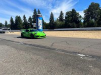
I actually took a GT3 RS around that track a few times this summer....forgot to post it! It was a blast and I loved having the throttle pinned down the straight with the exhaust roaring! :grinpimp:
 

Attachments

  • GT3 RS1.jpeg
    GT3 RS1.jpeg
    350.1 KB · Views: 22
  • GT3 RS2.jpeg
    GT3 RS2.jpeg
    501.4 KB · Views: 22
Sounds like the rich guys are willing to fly in and pay big bucks to take a training course, and then get to drive these things……
I’ll pick his brain next time I see him!!!!
:smokin::smokin::smokin:
 
First draft of the airbox design - this is a very rough first attempt. This was an exploration of space and size of filter I could cram into the volume. After searching through the K&N catalog with my overall generic dimensions, I found a handful that would fit in the space:

K&N Air Filter Dimensions search.jpg


After playing with 3 different sizes and designing the filters in CAD, I threw together the quick housing and started laying it out in reference with the scan. I'm not happy with the slope of the airbox where it passes over the throttle body. Not great for consistent airflow, and I'm out of room. I may have to take the compromise and just go with it, but I'd like to research airflow and how a sloped airbox will pull the air. I've seen a few OEM airboxes with sloped bottoms, but I don't recall one with this steep of a slope and this close to the filter. Of course, I could put this design into CFD and run a flow simulation....which I might do....but again.....laziness. :laughing:

It'll be a tight fit to keep the OEM vented wing cover. I would design a snap-fit interface for the OEM cover but I also want to play with a ram scoop, both a high and low version. Low for street so it blends into the bodylines, and a high scoop for use with a wing for the track. We'll see, I mostly want to lower IATs and mount a puller fan to sweep air into the engine bay.

Anyway, take a look and I'm open to feedback.

996 LS airbox v1.0 early render2.jpg


996 LS airbox v1.0 early render4.jpg


View from behind the engine

996 LS airbox v1.0 early render3.jpg
996 LS airbox v1.0 early render5.jpg


996 LS airbox v1.0 early render1.jpg
 
After going back and forth on the first design, I decided I didn't like the sloped airbox. I should put it into CFD to verify, but we'll see if I get around to that. I thought about two filters, and even saw the Hengst E1056L used in another custom airbox, so I played around with those and looked into other sizes that would fit. After trying to fit two separate airboxes with a Y, there just isn't enough space due to the LS3 throttle body actuator size. It's blocking a Y pipe...if anyone knows of a low profile DBW LS throttle body, please post it!

996 LS airbox v1.0 early render6.jpg


So, back to a one sided airbox but I need to know how much air filter area I need. I referenced my conical air filter and calculated the surface area to be around 110 sq in. I think this is on the lower end of the spectrum for a healthy V8 engine, and the long thin filter above is around 125 sq in depending on actual filter area. However, these numbers were based on overkill flow numbers for dirt accumulation when offroad. If this car goes offroad...I'll be designing a different setup.

Researching the flow rates of modern V8 engines, I see the general rule is intake speeds are 100 m/s or ~224 mph for standard engines and 115 m/s or ~258 mph for race engines. The formula to calculate surface area needed for an air filter is based on air flow rate. I did some maths, then cross checked here and found at 7000 rpm my flow rate should be about 700 CFM.

To calculate the required surface area for an air filter, you will need to know the air flow rate (in cubic feet per minute) and the air velocity (in feet per minute), then use the formula: surface area = air flow rate / (air velocity * 60).
Reference: https://www.physicsforums.com/thread...e-area.987902/

For LS engines, I'm using 224 mph (100 m/s). 700 CFM/ (224 mph * 60 mins/hr) = 0.052083 cubic feet or exactly 90 cubic inches, or in a filter's case, 90 square inches. This is at least a 9 x 10 inch filter. A conical filter, like the Uni filter on the car now, is 6 inches in length with a ~3 inch radius. Area for the outside of a cylinder = 2*pi*r*h. For my uni filter, this is 113 square inches. Like I said, I like to run larger filters on my cars, essentially to over-filter and offer more than enough air, but this is a street car, not my Raptor or race Jeep. So I think I could reduce filter size, cross reference other platforms filter sizes, and make this my min filter size needed and design around that.

So, here's version 1.2...this is a 11.5x9.0 filter and fits the bill for at least 90 sq in. and was used in up to 4.0L Dodge Nitro applications. I'd like it to be bigger, but this is the largest I can fit into this space without significant compromises somewhere else. I would say this makes a good street filter for casual driving. I'll want to take a high resolution 3D scan of the engine compartment only and ensure everything fits, and I'll order a filter to scan and finalize the CAD before 3D printing an initial prototype. Of course, I have to add mounting tabs and incorporate the spoiler cover.

Very open to feedback here as it's my first airbox design and curious what others have learned. :emb: My next idea is to expand the side of this new design with a slope for a bit more air filter area in the even it's needed and the engine would pull it from available space if there's a reduction in the closer areas.

996 LS Airbox v1.2 maxed one side filter1.jpg
996 LS Airbox v1.2 maxed one side filter2.jpg
996 LS Airbox v1.2 maxed one side filter3.jpg
 
I would try to make the transition from the round inlet to the actual airbox a lot more gradual. Other than that you need to get crackin at it!
 
I would try to make the transition from the round inlet to the actual airbox a lot more gradual. Other than that you need to get crackin at it!

Sure, more gradual transition - although this style is seen in OEMs and the only optimization would be to run through a CFM sim and ensure there are no major changes to airflow above ~10%. Remember, this is not a tooled part, this will be 3D printed, so any complex geometry becomes a risk to both part strength integrity and print complexity issues. Smoothed and angled transitions are nice, so are big fillets and chamfers - but they don't print well.

I was thinking the same.

gtxracer2
Mind if I give it a shot?

First draft of the airbox design - this is a very rough first attempt.

:flipoff2:
 
After going back and forth on the first design, I decided I didn't like the sloped airbox. I should put it into CFD to verify, but we'll see if I get around to that. I thought about two filters, and even saw the Hengst E1056L used in another custom airbox, so I played around with those and looked into other sizes that would fit. After trying to fit two separate airboxes with a Y, there just isn't enough space due to the LS3 throttle body actuator size. It's blocking a Y pipe...if anyone knows of a low profile DBW LS throttle body, please post it!
Remote it.

You could move the TB to the middle of the intake piping no problem and / or use a DBC cable with a remote actuator


You could also make a Y that bolts directly to the intake and use smaller 2 DBW TBs like 80mm from a BRZ which are compact and well supported in the aftermarket world.
 
Put in a second airbox, run a tube from 1 box to the other. Y pipes that close to the TB fuck up the flow. Better off with a single elbow.
 
Sure, more gradual transition - although this style is seen in OEMs and the only optimization would be to run through a CFM sim and ensure there are no major changes to airflow above ~10%. Remember, this is not a tooled part, this will be 3D printed, so any complex geometry becomes a risk to both part strength integrity and print complexity issues. Smoothed and angled transitions are nice, so are big fillets and chamfers - but they don't print well.


:flipoff2:
I am Admittedly :homer: when it comes to 3D printing.
 
Remote it.

You could move the TB to the middle of the intake piping no problem and / or use a DBC cable with a remote actuator


You could also make a Y that bolts directly to the intake and use smaller 2 DBW TBs like 80mm from a BRZ which are compact and well supported in the aftermarket world.

Great ideas, overall the complexity of that setup is too high. I don't want to deal with dual TBs and I don't want twice as many parts to fail in the intake system. The LS3 throttle body is proven to be reliable and I'd like to stick to it. I also don't have to program the BRZ TB parameters in the Holley software and deal with yet another custom part or setup. Simplicity is key here.

Put in a second airbox, run a tube from 1 box to the other. Y pipes that close to the TB fuck up the flow. Better off with a single elbow.

I like this idea, I was wondering if this would work or if I'd get enough flow between the boxes. I'll put together a design and see how it works.

I am Admittedly :homer: when it comes to 3D printing.
:beer: no worries! A resin printer (SLA) or powder sinter (SLS) could handle most any shapes but those are $$$ especially at this size. FDM (filament) is cheapest for a part this size.
 
Also looking at a smaller DBW TB, but again, unsure about reliability with these aftermarket TBs. Also....$750 is a lot.

 
Great ideas, overall the complexity of that setup is too high. I don't want to deal with dual TBs and I don't want twice as many parts to fail in the intake system. The LS3 throttle body is proven to be reliable and I'd like to stick to it. I also don't have to program the BRZ TB parameters in the Holley software and deal with yet another custom part or setup. Simplicity is key here.
uhhhh
Easily changing parameters is literally the reason why you'd get an aftermarket ECU.


Also looking at a smaller DBW TB, but again, unsure about reliability with these aftermarket TBs. Also....$750 is a lot.


103mm TB is way too much for your engine.

As far as reliability I haven't heard many bad things about Nick Williams, they are generally considered to be good units.
 
Top Back Refresh