C.R.D
Active member
- Joined
- Nov 2, 2023
- Member Number
- 7045
- Messages
- 31
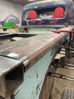
Hey everyone, So I have been building my 51 Ford rock crawler for a few years now. This past January there was some significant changes in my personnel life that have allowed me to spend more time building this project. So here is a run down of what I have done and where this is going.
The cab is a 51 Ford F4 pick up truck cab, the frame is a 01 GMC Serria along with the 5.3 LS that came in that truck, and the box came off of a 51 International Pickup. Before I get to far into this, I am pretty sure I started this build thread on here years ago, however I can not find or remember what my name was etc. for that account.
My goal for this build is a capable rock crawler, that is street legal, safe, and a head turner.
IF you want to see what I am working with, what my thought process is, and where I am to date here is a link to the YT channel.


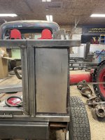
 fender may well draw enough attention that the square rear corner is fine