This has been in my head lately. It's been discussed many times before on this board. Trying to find a solution for low ride height, max wheel travel and not cutting the tub for shocks to clear.
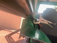
This complicated mess or dragging trailing arms on the rocks. 9" axle, 40" link and a 8-6.5 unitbearing as the pivot.

This complicated mess or dragging trailing arms on the rocks. 9" axle, 40" link and a 8-6.5 unitbearing as the pivot.

 Ask me how I know