What's new

1978 F250 400 Dual Fuel

weird, having some issues try to put up pictures. let's see if putting them as attachments first works better...

Milwaukie drill done shit the bed. it's had a long hard life.

20221023_152700.jpg


Door speakers in the door, had to enlarge a pre-existing hole in the top for the tweeter and these 6.5" are slightly larger than the old 6-1/2" they replaced, so a little bit of sanding and drilling for them as well.

20221023_155832.jpg


The tweeters pop apart and can be mounted in the round things which allow them to change angles and be pointed, that i'm using currently, and another set which are much more flat. come with a sticky pad so you can just plop them anywhere too. options are nice.

20221023_162615.jpg


and noticed this pretty decent fuel leak while playing around with the stereo. the fuel lines are not great, somebody put in soft lines rather than fixing the hard lines many years ago and they are pretty cracked up now. Oddly, it hasn't leaked like this before or since. Dropping the tanks and replacing the lines are a sooner rather than later project though.

20221023_172527.jpg
 
after much thinking and reading and even a few attempts as measuring, made a sketch plan for a speakerbox. this is my first attempt, it's been many years since I had subwoofers in a car and just went through the rear deck on that. that setup had many issues :laughing: in total, used just under 2'x4' of 3/4" MDF

20221029_121000.jpg


Slowly learning, cut out my circle first

20221029_122656.jpg


I can almost make a smooth line with a jigsaw :rasta: I own freehand routers, never tried using one though :homer:

20221029_123508.jpg


My wormsaw is missing the nut that locks the angle down for the guide, turns out. Also I was mostly done when I realized it's possible to clamp down a guide rather than trying to draw long straight lines by hand :laughing: so, corners nearly line up perfect.
Sandpaper, foam and fabric will fix this

20221029_135640.jpg


bunch of reading and such, put in some 2x2 blocks for bracing. seemed like a good idea at the time :homer:

20221029_145454.jpg


Says to seal the seams with silicone. What you are supposed to do is put in the goop BEFORE you put internal blocks in place. Things I know now.

20221029_151206.jpg


1/4" fluff/batting/pile on the face and 1/2" foam on all the other sides. Should've probably done the bottom as well but didn't. Making the box square rather than wedge shaped, so trying to keep height and width to a minimum.

20221029_153741.jpg


Put the rest of the poly fill inside the box. Apparently the goal is between 1 and 1.5 pounds per cubic foot of volume. So that'd put me about 1/2 a pound max. Ended up with under 3 ounces. #CloseEnough

20221029_154302.jpg


cut out a hole in and folded the fabric back under.

20221029_160958.jpg
 
and test fit, seems to do the thing

20221029_161439.jpg


2 ohm dual voice coil, 4ohm minimum required for the amp in bridged mode.

20221030_102034.jpg


Made a little mount tab for the top. originally planned on making 3 tabs, ended up just doing the one, which should be fine.

20221030_104937.jpg


hacked away with a razor at the fabric and foam so that I could plop in an insert into the housing

20221030_105917.jpg


Cleaned up the rear floor, there is a few undulations along the floor, which is ultimately why I decided against making floor tabs :laughing:

20221030_110846.jpg


1/8" rivets for the rear wall

20221030_111418.jpg


And i'm not entirely sure how it ended up so far off, but some gentle taps with the hammer and a block of wood formed the tab nice and tight into place

20221030_111635.jpg


The cheap-o 8 gauge amp kit came with a real small ring terminal for the ground. Hacked up a 12 gauge 3/8" loop onto the end. Thing only runs 25 amp fuse so it doesn't really need all that wire.

20221030_121145.jpg


added some heat shrink to help it not fall apart so quick


20221030_121336.jpg


And went ahead and tapped up and cut off the tachometer. This way the connections are all still there and it can be hooked up as needed in the future, and also now I can use the tach itself for whatever else. cleaned up the wiring a bunch

20221030_140424.jpg


and that's all the pictures I took apparently.

Went ahead and freed up a bunch of length from the door speakers so the rockford amp is now mounted the correct direction and made an absolute mess routing wires under the vinyl floor. Not looking forward to pulling that up one day to de-rustify the floor pans.

Spent some time playing around with speaker settings. Despite not being able to be very loud, I was able to get it to a point it sounds pretty good. The kiddo was amazed at how quiet it was outside the truck versus how loud it can get inside the truck, so that's a decent win :smokin:

Door cards will be the next interior thing, but that may be a ways off yet

edit: Using test tones to set amplifier gain

this is a good article to explain stuff


this makes sense also


edit: using the bottom link suggests the following maths, with the head unit volume knob set at a level below clipping. looks like I'll need to poke around and work and see if I can find a O-Scope laying around

4 ohm speaker x 250 watt target = 1000 then square root = 31.622 volts A/C target for subwoofer at 40hz 0db test tone

4 ohm x 65 watt target = 260 then sq rt = 16.12 volts A/C target for door speaker

4 ohm x 75 watt target = 300 then sq rt = 17.32 volts

E = √PR, where E is the A.C voltage, P is the power (watts) and R is the Resistance (Ohm). Follow these steps closely.

100w is 20vac
200w is 28.28vac

edit3: alright, i'm about done reading for the evening. going to just run the 1khz test tone and see if I can use that for setting the volume and gain for regular speakers. Then I guess i'll run the 60hz test tone and use the multimeter to see if I can get the 31.62 or so VAC and see what happens.


and then try out the DVOM on VAC to set the crossover with a test tone :rasta:


for LPF just play the test tone u want to set the crossover to. turn it all the way up and then turn down until a digital multimeter decreases to half of what the voltage up with the LPF all the way up. do the same thing with the HPF except youll have the HPF all the way down and youll go up until the voltage drops to half of what it originally was.

17 year old quote from above
 
Last edited:
well, quick note update playing around this morning.

used the test tone generator on the phone, it was entertaining. the dash speakers vibrates at 78hz and the head unit clips 400hz and 1000hz at 34 on the knobby, turning up the volume on the EQ doesn't seem to clip the signal, at least for as high as I can stand, so that's nice to know.

i had been setting the head unit to 30 as a max and will continue to do so, nice to verify that i'm not totally crazy. For setting the gain on the dash speaker, started low and adjusted until the noise changed. probably was, it wasn't a clean change. as soon as the 1k hz changed tone, started going back down with the gain and it didn't clean back up. it was between the 3 and the 5 on the knob the first time it changed, so i've got it set below the 3 now and calling it a day. Dropped it down to 78hz on the tone generator, and then adjusted the high pass filter until I could no longer hear it rattling in the dash due to the poor mounting. ended up just above halfway between 50 and 250hz.

for the door speakers, same process as above, except the gain ended up just above the 3. this is pretty much where I had had it before I started, so that was interesting. Set the tone generator for 100hz and adjusted the high pass filter until I could just hear the sound start to drop off. Ended up near, but a little lower than the dash speaker.

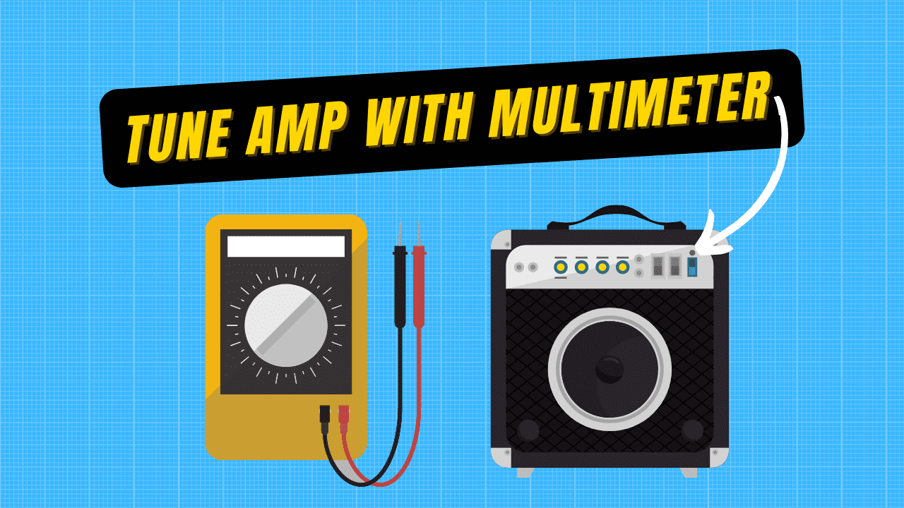
then the subwoofer. oh buddy, made me sad for a while. grabbed my cheapest multimeter because it was handy, unhooked all the speaker inputs except for the sub from the EQ, then unhooked the sub speaker wires. In shooting for the 31vac from the above articles, I ended up with the gain on 7 of 10 using a tone of 60hz. Then set the tone to 100hz and adjusted the low pass filter until i got about 15.5vac. again, using the articles above the explanation was that half the volts would be equal to 3db slope drop off. This put my LPF at 80hz. Then hooked everything back up to see if it worked.

absolutely terrible. crazy humm permeating everything. Alright, I "must have my gains too high" so I turned them all back down. still there. played with front/rear/side/side and eventually isolated it mostly to the sub but it still wasn't right with the sub totally out of the loop. checked connections, everything seemed fine. reset all the knobs back to where they were before I started, still not any better.

threw in the towel and drove home from the open lot down the block.

at the house, figured i'd check one more time to see if it got better turning it off then back on. turned it on, no music, obvious hum.

Opened up the phone.....fucking 100hz signal generator was running in the background THIS WHOLE TIME :lmao:

Turned it off and it cleaned up pretty good! re-twisted the knobbies to about what they were and called it a day. I need some coffee


edit: going to try these out. $30 for some inline high pass filters at 50hz for the sub.


why 50hz and not 30 hz? well, cheap sub is why. The below chart is from the R2D2 product brief. The sealed box that i'm using is roughly the volume of what they used (0.59 cf). The Xmax, the maximum travel of the sub itself before hitting 10% total harmonic distortion, is only 6.5MM. the Dashed blue line shows the travel over on the right hand side of the graph, and this speaker hits that maximum travel about 70hz (at max volume) as well as a sealed box tuned resonance at 57hz and -3db loss at 58hz. Free air resonance is 34.6hz, so i'm likely much closer to the 60hz figure than the 40hz figure. Since this speaker is already rolling off at the bottom end, i'm more than happy to start really cutting it off down there and call it a day. Doesn't seem like it will get me much anyways. Of course, this does mean that I will give up a ton of tone when listening to deep bass. Should be a reasonable tradeoff.

r2d2 tech spec.png
 
Last edited:
and noticed this pretty decent fuel leak while playing around with the stereo. the fuel lines are not great, somebody put in soft lines rather than fixing the hard lines many years ago and they are pretty cracked up now. Oddly, it hasn't leaked like this before or since. Dropping the tanks and replacing the lines are a sooner rather than later project though.

20221023_172527.jpg


Welp, it's been almost a year since that fuel dump, it also lost enough fuel when filling up the rear tank that I stopped using the rear tank for a long time. :laughing:

So got back after it siting for many months, wife drove it once is all.

Damned thing fired right up after a bit of cranking to get fuel back up :smokin: and then damned Niagara falls underneath :eek: so let's get them tanks down.

These soft lines were about the newest on the truck and even they were starting to split from disuse.

20230911_140112.jpg


Tanks cleaned up pretty good with the hose and a scrub brush. Sprayed the first bottle of stuff in the garage on them as well, turns out it was bleach :homer: oh well.

20230911_150958.jpg


Pretty happy with this slate blue color. Can't remember what I bought the can for, but I'll sleep better knowing the top of my furl tanks are pretty:laughing:

20230911_160531.jpg


This picture will be important later, I've got the rear tank as my main on the dash switch which is the bottom position, mid tank is aux on the top position

20230911_152453.jpg


Saw this thing, wasn't sure if it was important

20230911_164903.jpg


After taking it down, it's just a dead head that appears to be the factory takeoff for trailer connector. Kind of neat

20230911_165253.jpg


And spent a little bit of time bending up lines. Going to use as much hardliners as possible, just going to run 5/16 everywhere and ordered some 3/8 barbs and soft line for the connections on the tank side of the pump, 5/16 is standard for the carb side. Just didn't want to buy another roll of 3/8" hard line :homer:

20230911_192824.jpg


Also figured I'd move the filter to the rear of the carb. *one of these days....I'll make some actual mounts for the line, otherwise it is up off the heads and away from the block, so shouldn't be any heat issues.

20230911_193125.jpg


Also figured I'd just run the first half of a double flare to make a softer bubble, since I don't have any bubble anvils and this is easier than double flare for something that will see 5psi and a hose clamp.

20230911_192219.jpg


Going to take my sweet time getting the rest of it done, pretty happy otherwise with how it held up during storage. Trans and power steering leaks seem to be not any worse :smokin:
 
and back to bending up tube. wouldn't been easier to just use 3/8" for everything :laughing: worked backwards from the pump to the tanks and moved some of the OEM hardline break spots.

pump to the steering box

20230914_155626.jpg


8' long section to go from the steering box to the rear shock mount

20230914_163308.jpg


and the fun angled corner from the shock mount to the tank selector solenoid

20230914_175015.jpg


and just bent by hand to trim them all in and catch the factory clips. probably should have grabbed 3' instead of the 2' of 5/16" that I bought, so I reused some of the best sections of the old stuff. :homer: also ordered a bag of the spring clips because I thought it would look better than the screw clamps. apparently they have delayed in the mail for a few days, not sure if i'll replace these or not

20230914_175943.jpg


tried to keep most of my soft junctions short

20230914_175952.jpg


going behind the steering box is super easy when the box isn't installed, went ahead and used soft line there rather than remove it

20230914_180034.jpg


going to go to a 3/8" hose barb iffin it ever shows up or tomorrow once I go to the store at the pump. this outlet was the most persnikity about accepting 5/16" hose

20230914_180101.jpg


otherwise, waiting on some 2-1/4" to arrive at the store tomorrow for the filler necks and it should be running again :smokin:
 
Tool way too long to figure out how to get the front tank back in :laughing: me and a floor jack finally figured out it needs to start at an angle and towards the rear about 6" to then slide over and behind the carrier bearing mount :rasta: also ended up with a decent distortion in the filler hose, which is admittedly not fuel rated, so if it won't take fuel from the pump very well then I'll get it swapped out with the proper small bend and grade stuff.

Also the vent lines are certainly near 5/8 and not 3/4. Pain to stretch the 3/4 across.

20230915_180511.jpg


This line was in this spot previously, comes from the lift gate and went around the tank to inside the frame rail. Lots of exposed and degraded copper, always figured it was a ground.

20230915_165213.jpg


Turns out it is a hot line from the battery side of the starter solenoid. Heard it cackle pretty good when putting up the rear tank, figured it tripped whatever fuse and would be dead/fine. Leaned on tank and it crackled again, no fuse :laughing: So that will need to be replaced to get the gate back to working

20230915_164541.jpg


But hey, runs and drives now. On to the next commuter and then back to putting the farm truck together


Edit: welp, had a couple issues. Ran out of fuel last night, figured the pump had dried out.

Went to toss on the new pump and noticed the soft line was more kinked than I had left it, dang.

20230916_142057.jpg


And only having a 90* tool gives not the best bends for making circles and stuff. Wanted to have enough length to account for vibrations and such. Good enough for brake flex, probably good enough for engine shakes.

20230916_141932.jpg


Super ugly but with 2" of soft line at least I won't have to worry about kinks.
20230916_144537.jpg


And I'll just save the new pump for the farm truck. This fixed my fuel supply issues.

Made it to the gas station, rear tank works as intended, front tank does not. Way too slow, going to go ahead and order the correct pre molded hose for that filler neck.
 
Last edited:
and so i don't forget whenever I get around to it, the lift gate is supposed to have a 150 amp circuit breaker
 

Attachments

  • Tommy Gate Owners Manual.pdf
    1.1 MB · Views: 2
  • Tommy Gate Parts Drawing.pdf
    1.1 MB · Views: 2
Alright, finally went ahead and made some progress on the door cards :rasta:

Here is how it begins, been like this for a bit.

20231005_140624.jpg


got a bit kerfluffald trying to figure out how I was going to get somewhat close. A better idea would have been to leave an access hole in the main panel, then just use a sharpie to mark them through the holes. So instead, I approximated some hole locations using a tape measure and then measured from 2 holes to find new locations. Pretty much worked out. arc intersections for centers.

20231005_145939.jpg


most of the major points laid down. This is some 1/4" thick stuff that reminds me of cheap shelves or racks or something. It's got a dark hard/slick surface on one side.

20231005_151424.jpg


Better idea would have been to start with the arm rest holes and base every thing else off those. This is when I realized I made a dumb decision :laughing:

20231005_155050.jpg


cheapo $40 rivnut gun. Always wanted one, works as well as I had hoped.

20231005_170323.jpg


and the 10-24 rivnuts fit into the factory quick trim holes

20231005_170808.jpg


Figured I'd try some transfer paper to see if it would locate all them holes for me

20231005_172637.jpg


and the answer is not really. Had I redone this with the craft paper instead of tissue paper, might have worked. This at least got me close enough to investigate with a small drill bit until I found what I needed.

20231005_173040.jpg


1/2" foam, more of that flower curtain stuff to match the headliner, and the kickass 3M Super77 general adhesive

20231005_184916.jpg


and installed.

20231005_192513.jpg


Adding a pocket would have been a good idea, not sure if I'll ever go back and make that change. Don't have an armrest, i'd like to see if I can whittle one out of a chunk of wood. Not sure how that would work or happen or look like. Should probably get some of the wider upholstery washers for the fasteners.

Regardless, makes me happy :flipoff2:


edit:https://acousticstoday.org/wp-content/uploads/2016/12/Highway-Noise.pdf

"The spectral content for passenger vehicles typically peaks and is dominated by frequencies around 1,000 Hz. Spectral content for heavy trucks typically peaks and is dominated by frequencies from 500 to 1,000 Hz."


4" thick acoustic panels claim noise reduction coefficient

125hz 0.39
250hz 0.61
500hz 0.91
1khz 0.79
2khz 0.95

2" claims

125hz 0.2
250hz 0.29
500hz 0.66
1khz 0.8
2khz 0.89

thinking about putting some of this on the backside of the door card into the hole there where the window goes, need to see how much space there is. Open cell foam should dry out quick and easy enough, never have noticed too much water getting in there. Seems cheap and easy to get some road noise down.
 
Last edited:
Welp, I'm mostly happy with the arm rest :laughing:

made a bunch of drawings on a piece of 12"x2-3/4" MDF trying to see if anything would make sense. Still think a solid block of 4x4" wood carved down to shape would be more better.

20231006_115114.jpg


Decided on a meat clever of sorts :rasta:

20231006_125319.jpg


Did some digging around, couldn't find both of the steel factory angle bracket things. Bent up some scrap aluminum. It's thin and not nearly as sturdy as i'd like it to be. Certainly seems good enough though. If it ever fails or bugs me more I'll pick up and whittle down some 2x2" angle steel

20231006_125327.jpg


went about all the way around with the first layer of half inch, then did the top half with another layer of 1/2" to build it up.

20231006_153009.jpg

used a bit of cord to tie the foam tighter around the handle neck

20231006_153810.jpg

Figured I'd try to actually make a template for the wrapping out of fabric. Completely neglected to mark a reference, so it almost did what it was supposed to


20231006_160942.jpg


and installed. a year or two ago my sister gave me some leather and fake leather from some couch repair that never happened. It's mostly not real leather with a real leather band. this would have been a bunch better if I had sewn the "handle" into a slip on piece. In the event I need to do it again, i'll give it a whirl that way. For now it's all glued. Left enough material to stable it on the bottom if I find more staples around.

20231006_165148.jpg


anyways, serves it's purpose and it's been a long time since i've had a door and armrest that wasn't broken or gone :smokin:
 
another day of tinkering. didn't think i'd spend as much time on this as it ended up taking today :rasta:

Been wanting to move the one amp for a while which is why I'd left the leads long, never could figure out where I wanted to put it. Had to extend the speaker wires a bit. Put the old antenna mount to use as a wire holder. need to cut those bolts off one of these days.

20231008_113141.jpg


wanted to make these 6 wires flat to fit under the floor mat a bit easier, figured I'd do a flat braid.....didn't take much length to realize no way in hell was I going to make it. So twisted them up in their pairs and did a regular 3 strand braid instead for the rest of it.

20231008_121622.jpg


and since I borrowed some wire out of the box of old wires and had to uncase it, figured might as well use the split loom and cover up a bunch of the leads. Moved the small amp to the speaker box and put the other where the small one used to live. After this picture I moved the power and ground lines for the rockford as they were in an oddly stressed position here.

20231008_163605.jpg


and putting everything behind the driver seat leaves the space behind the passenger available for...something. Umbrellas? I dunno. Need to pop in some clamp to hold the wires out of the way.

20231008_163630.jpg


and the real reward, got a couple fist fulls of wire removed, rerouted and otherwise cleaned up.

20231008_165522.jpg


20231008_165533.jpg


Interior finally feels like it is coming along. Feels better to be in.

20231008_165553.jpg


and since i've been making things better a little at a time, went ahead and splurged for some $6 new door striker bushings. Previously they had several layers of duct tape build up/worn through.

20231008_181919.jpg


It's a T50 bit to remove the striker, no need to though. the thick washer won't pass the threads :homer: the dorman 38424 kit comes with long and short bushings, the long ones need to be trimmed down about an 1/8" but are the correct diameter, the short ones are too fat for the door latch. Figured on cutting them at an angle so that maybe they hold up longer :confused: I dunno.

20231008_183117.jpg


between freeing up the hold open spur and getting this bushing on there, it's like having brand new doors. Amazing difference. Wish i could find my sound meter, it would have been interesting to see how loud the cab was when I first bought this thing compared to now.

anyways, happy columbus day! I hope you all get lost looking for spices at the grocery store and come back lottery winners :flipoff2:


edit: Factory Interiors - Auto Carpet, Floor Mats & Accessories ordered samples from this place for vinyl and cut/pile. black and red. need to grab some sheet metal to make a whole slew of patches or floor sections. going to just toss the samples into the glove box for the next year or so.
 
Last edited:
Does it not thread off? The ones on chevys do.
nope. thought it would. nearly cut it off, thought better of it and just cut the bushing. It'll work until it doesn't, might see what heat does to the short ones in the kit. If it responds well, i'll hot iron them back together.

If not, it's still way better than before
 
nope. thought it would. nearly cut it off, thought better of it and just cut the bushing. It'll work until it doesn't, might see what heat does to the short ones in the kit. If it responds well, i'll hot iron them back together.

If not, it's still way better than before
I've also used heavy duty 4:1 heat shrink in place of that bushing.
 
Not sure what your problem is. I've replaced the striker bushing on more than one Ford truck of that era and the washer should come off. I don't recall it needing to be pressed of but if it does that shouldn't be a big deal.

I don't buy the plastic bushings. There's a particular standard size bronze bushing that fits the bolt and will fit the striker with just a tiny bit of turning.
Corrosion probably, toss them in the wife ultrasonic jewelry cleaner would probably be enough to free it up. That's also a once these bushings fail problem
 
Welp, glue alone didn't last long as expected on the arm rests. Took a couple warm days with the windows up to unfold it completely. Never did find my fabric nails so had to wait until the weekend to pick up some more.

20231013_154806.jpg


and hammered my thumb several times before grabbing needle nosed pliers to hold these dang things.

20231013_160422.jpg


20231013_161930.jpg


and popped off this old mount going through the marker lense

20231013_164507.jpg


and the only reason i was messing with this thing at all, going to go ahead and address some more of this dang wiring nonsense. 3 times over the past week or so the battery has been 3-4v dead in the morning. Never had a problem after being parked for a few hours at work. Wasn't sure if it was a week battery being 5 years old, some abuse from shorting it a few times or if I was managing to draw down more power than my alternator was making.

Started off by going to get a new battery, thing passed load test showing 790 amps.

anyways, pictures of what i'm starting with. drivers side firewall corner

20231013_165325.jpg


passanger side firewall

20231013_165334.jpg


and so that i can remember what all went where on the starter solenoid

20231013_165338.jpg


and the back of the alternator. Alternator itself has been replaced probably in 2018 when the "new" battery was put in, looks clean. However, main charge wire has a couple broken strands and doesn't look pretty. So maybe it is not letting the max potential 60 amps through :confused:

20231013_165355.jpg


and also finally pulled the main power wire for the lift gate out all the way to the back

20231014_092420.jpg


20231014_092423.jpg


10img limit
 
and the olden style gate with the simple lever to go up and down.

20231014_092443.jpg


here you can see several of the areas where the wire was exposed, made for some interesting times with no fuse :laughing: After some thinking about it, I'm probably going to see how much of the old insulation I can knock off, then tape it up and put it into a sleeve and run it again. did pick up the 150amp circuit breaker for it as well.

20231014_094055.jpg


In the interest of getting things to where I can see them, pulled the wires off the propane dealios as well, just tied these up by their switch under the dash.

20231014_103604.jpg


red wire above went to that dealio, then turned into a blue wire further back. The black or brown, whichever color it is, was the one for the gasoline shutoff between the pump and carb and the yellow one is for "purge" and was just hanging out.

20231014_103755.jpg


Took several breaks to play with the solar eclipse today, pack of straws was fun

20231014_112449.jpg


These two very factory looking plugs run back to the mid frame trailer plug. unhooked them as they are spliced several times and just contributing to the mess in the corner.

20231014_120524.jpg


This switch has always been a source of curiosity.

20231014_123519.jpg


It switches these wires in the cowl, one on each side. Maybe it was once lights :confused: weird spot for things, removed for weight savings.

20231014_123939.jpg


there was enough quick taps on this wire that i'm pretty sure it is a keyed 12v rather than a constant hot. At least I hope so, moved my choke heater wire to this guy after cutting out most of the splices and such.

20231014_125151.jpg


and i'm not sure how to get this little light removed. Probably have to try the correct sized wrench, it's just tiny.

20231014_131723.jpg


This one was actually doing something, nearly.

The dual battery setup has a solenoid which appears to be identical to the start solenoid on the pass. fender. This light was above a tiny switch which ran the solenoid, it leads that the light would light up when both batteries were linked together.

There never was any pos/neg leads on the second battery so i never messed with it. If I were to go with this same setup, triggering the solenoid to close when the key was on would make more sense, then you don't have to think about it.
 
alright, after doing a whole bunch of wire chasing to see what was real and what wasn't, finally got back to the original thing. Attempting to change the alt charge lead.

This is the factory harness all cut open. The charge wire has a pretty long loop to it, which is where the in dash ammeter reads. I'm working off the theory that the large black/yellow line, which runs from the alt charge lead to the ignition switch, is the only thing I really need to relocate so that I can separate my batteries.

20231014_154655.jpg


Don't have the correct crimper, but do have this crimper. Don't have the correct ends either, these are either 8 or 10 gauge wire with 2 or 4 gauge connectors. Factory was a 12 ga wire. Just in the off chance at some point the alternator gets upgrade to more powerful junkyard version in the future. reused the 16gauge fuse link for now.

20231014_155706.jpg


Made the charge/ammeter loop the same length. Figure if it makes any change it would be lower resistance so greater swings on the dash gauge :confused: not sure, it didn't move before and I don't expect it to move now. Be neat if it did :laughing: Used a connecter of whatever type they are called that are common with solar panels because I had them. This will let me change the source for the vehicle power from either the start [main] battery or the coach [aux] battery. Don't expect to have to change it often or ever, but might as well have the option in case it doesn't work.

20231014_172108.jpg


Saw a hole in the frame, looked like a good spot to add a ground. Rivnut to the rescue.

20231014_174442.jpg


Positive terminal has been cracked for as long as I've owned the vehicle and was always annoying that both leads were black. Using up some of the 4ga stuff in the wiring pile in the garage and some new terminals. Also made a new ground for the battery to the engine block, added block to frame.

20231014_184602.jpg


Going to pick up some self tapping screws and/or another pack of cheap small drill bits and some cable clamps to tuck things back a bit. Passenger side firewall.

20231014_184608.jpg


Overall it feels a bunch less stressful to look at. Yeah, yeah, not super clean just way better than it was in my opinion :flipoff2: Never done, I like this stage better than the last

20231014_184613.jpg


Couldn't figure anything to do with all the massive factory plugs that remained on the drivers firewall, at least things are bundled now.

Removing the cruise control fully made a huge difference.

20231014_184618.jpg


Monday I'll be getting the "smart" battery isolator and wed-fri is when the new battery is supposed to arrive.

Need to pick up some 10 or 12 ga wire in red and black.

Plan is to have the start/main battery on the passenger side isolated. Alternator and starter should be the only things going there first. Going to run the 12v+ to the key and a 12v+ battery wire over to the driver side. batt 12v+ will go to the isolator. Keyline 140amp smart isolator, energized above 13.3 volts and decouples/opens below 12.8v on the main battery. Effectively isolating the batteries anytime the alternator isn't charging.

Ordered a chinese WEIZE 50ah LiFePO4 battery for the second battery. Having them isolated anytime the alternator isn't charging will prevent any chance for them to drain each other down and the lead acid will absorb/buffer any issues the Lithium-Iron guy would try to cause from a constantly charging alternator. The LiFe tolerates higher draw rates so it should be much better suited to running the tailgate.

Sitting in the parking lot listening to the radio with all the lights on until the battery dies also won't prohibit the truck from starting as well. That's the theory anyways.
 
Alright, forgot I had the actual year correct wiring diagram as well. Been looking at the 85, which has some more options.

wiring_78master_3of10.png


wiring_78master_4of10.png


20231014_154655.jpg


wanted to verify that I got the right wires pulled out and that leaving the rest wasn't an issue.

From the factory alternator harness:
main black/red line from the main charge plug with a 5/16" ring terminal
White/black with gray cap from alternator, goes to a plug with a green wire. The white/black line runs to the carb choke heater. (well, should with factory stuff)
Orange line with orange cap from alternator, goes to voltage regulator.
Yellow/black and Red lines measure two spots on the main charge line and go direct to the ammeter
Black/yellow, the heavier wire, goes with the 3 pin plug with the Yellow/black and red for the gauge. Black/yellow runs to the ignition switch for all keyed functions.
Yellow wire goes from main black/red alternator wire to regulator
Green wire out of regulator, labeled 904 green/red on the diagrams, and feeds brake indicator lamp, oil pressure lamp, fuel gauge selector, carb emissions solenoids and throttle actuator.

Which means that I'm not going to bother moving the green wire over to the coach/aux battery. no real chance for any big drains there.

Throttle actuator is mounted in the dash along the drivers side panel/wall behind the head light switch. It was unplugged and I plugged it in, so i'll just unplug it again.


Splice 208 is near the ignition switch, it is the Black/Yellow wire splice with a Black/Orange wire which feeds the headlight switch, and sends off another Black/Yellow that feeds the rest of the fuse panel.

alright, feel better about hacking into just the one lead in the factory harness.


edit: alright, might as well see if I can clean up a bunch of the splices and random wiring on the inside since i'm at it.

wiring_78master_2of10.png


starting with the Fuse box, the image at the upper left of the above diagram is rotated 90* counter clockwise from how my box is sitting in the truck itself. re-writing stuff here to make it make more sense in my head and to be faster/easier to read than trying to decipher and zoom in on the image every time.

Fuse 1 - blank
Fuse 2 - 3 amp PRND/Instrument cluster/panel illum - fed by blue/red line from headlamp switch leaves Blue/Red # 19
Fuse 3 - 35 amp HVAC switch - fed by orange line from key run & accy position

Fuse 4/5/6 bussed together, fed by red/green at key and red/yellow after splice at fuse box key run position
Fuse 4 - 7.5 amp seat belt - green/blue #504
Fuse 5 - 7.5 amp emissions solenoid [opportunity fuse for key 12v run source] Blue #932 & red/yellow #640
Fuse 6 - 7.5 amp aux fuel selector - leaves red #973

Fuse 7/8 bussed together, fed black/yellow direct from battery and always hot
Fuse 7 - 15 amp dome & courtesy lights, cigar lighter [opportunity fuse for 12v always on] - leaves green/yellow #54
Fuse 8 - 20 amp emergency flashers, brake lights - leaves on red/white #383

Fuse 9/10/11/12 bussed together, fed by black/gray lead from key run & accy
Fuse 9 - 15 amp turn signal flasher leaves yellow #0
Fuse 10 - 20 amp accy feeds buss bar for 9/11/12 fed by black/green # 297 - origins at key on & accy
Fuse 11 - 15 amp reverse lights, windshield washer fluid leaves white/black #950 & white/purple #138
Fuse 12 - 7.5 amp radio leaves yellow/black #137

edit2: added lines out from fuses
 
Last edited:
Went to the store, oreally didn't have any heavy duty electrical tape or loom, grabbed some liquid electrical tape to give it a shot. Used the dykes to cut back the dead insulation and bent the wire the whole way down to find all the hard spots. Cleaned it up and started brushing on.

First coat.

20231015_105651.jpg


and went all the way to 7 coats to get a decent build up. Apparently it wants 10 hours before putting it into use, instead of that I gave it an hour or two and wrapped it with electrical tape and covered with regular bumpy split loom.

20231015_130147.jpg


Reinstalled onto the pump motor, took a hole in the bottom instead of the original one on the back of the box since i'm going the same distance to the opposite side up front.

20231015_131919.jpg


went up and around the frame/fuel tank. Through this hole and then along the inside frame rail all the way up, following the trailer brake lines. This is a far less exposed route than it originally had. Hopefully it makes another 20 years :rasta:

20231015_133812.jpg


added the 150 amp fuse to the fender and swapped out the solenoid for an isolated stud. Going to need the battery and isolator before re-arranging all this stuff. Added back a bunch of chaos :laughing:

20231015_143101.jpg


and picked up some 10 gauge wire as well this morning, labeled some white tape just in case it lasts. Main battery and Aux battery connections options.

20231015_112759.jpg


enough of a mess made, time to head inside and finally figure out why there is a white/black wire jammed into the battery side of a fuse :homer:

this through the middle and wrap around splice is rather common on this truck. Sending power direct to the brake switch bat+ side

20231015_145425.jpg


Removed some more multi-splice wires. The green connector is to the factory radio, yellow line shows good connection with the Radio fuse, sent that to the keyed 12v for the stereo. The green (looks gray) line behind it is for the cigar lighter fuse and should be a constant 12v, yellow line goes to radio 12v constant and red line goes to 12v power outlet and usb charging port under the dash.

20231015_160410.jpg


and figured what the hell, mounted the center dash speaker with it's magnet instead of trying to mess around with the unalignable holes. Going to need to make an adapter for it at some point to be correct, not today. It's a 5x7 and about 1/8" too wide

20231015_170713.jpg


Working my way from right to left, took off the cover for the mystery gray "fuse box" by the brake pedal. It's a pretty sweet fused relay for 2 things. Battery input on the side, out to "lights" on the bottom and in from "switch" on the top. No switches hooked up and a jumper wire from Bat to one of the lights.

20231015_162645.jpg


picture limit
 
Following the wires under the floor mat, they go right to this factory plug.

20231015_162649.jpg


which is curiously located right next to the floor high beam switch. Switch has never worked and the truck even came with a new one the previous owner "never got around to replacing".

20231015_163144.jpg


well shit, probably help to actually plug it in. It's been neglected for some time, removed from the floor and applied sand paper to the contacts and the meter. Switch does the switching things on demand :smokin: Connection between red/yellow and green wires runs high beams, red/yellow and red wires runs low beams.

20231015_163946.jpg


with all that remains tucked up and out of the way I took some pictures of the inside of the dash. Less of a jumbled mess, not going to case everything up anytime soon though. The red wire tapped into the bulb is a spare power take off in case I want to trigger something with the head lights.

20231015_170723.jpg


20231015_170727.jpg


20231015_170731.jpg


and got it all put back together.

20231015_174838.jpg


20231015_174902.jpg


No longer do I have every option available from the JC Whitney catalog in 1978, but I finally know what everything there does :laughing:

From the left: Wiper delay box, working :smokin:
Selector cable and fuel solenoids for the propane, wires bundled up by the controller, not working
Little red light that I can't remove, wires bundled up, not working
Manual choke cable, not working
Trailer brake controller, working :smokin:

12v+ and usb power outlets and stereo stuff. Should be working, used to work, no longer working :confused: need to figure out why fuse panel isn't putting out power


However, it didn't catch on fire when I started it after all this.
Liftgate work and sounds better than before.
High Beams work.
Ammeter works!?!?!?! Danged thing moved when I started it, showed charging. Shut the truck down and turned on the lights, moved to discharge. My neutral rest for the needle is just almost a full needle to the charge side of the centerline, but gosh golly, feels like I've never seen it move until now. Super exciting.
 
Last edited:
Going to work this morning and the radio fixed itself and came back to life. Figured it was fun that it fixed itself, after doing some expirements while driving I discovered that I had wired the 12v constant to the dash light dimmer switch.

The wire I thought was gray and told myself was green was actually blue with a very faded red stripe. Since it is bused with the cigar lighter fuse, I checked the wrong side of the fuse when the battery was out.

Green with yellow from fuse 7 is what I need, runs courtesy lights, cigar lighter and glovebox light. Could not find where this dropped from the harness to the lighter but did find where it goes to the glove box. Haven't ever had this light, plug was tucked up in the dash. Verified with the meter 12v constant and fuse 7 output end.


20231016_143356.jpg


Over on the other side is this plug, black and green wire and 12v keyed. Somebody at some point cut the plug into 3 parts, mighty convenient. Going to reuse the green wired one to be close to the colors.

20231016_143207.jpg


And labeled the blue wire as dash light, used some more green wire to come from the glovebox across and hook up the stereo, 12v outlet and USB chargers.

20231016_150108.jpg


And now all that stuff works :rasta:
 
20231017_083652.jpg


20231017_083920.jpg


20231017_084518.jpg


20231017_084910.jpg


On the 7 band equalizer, ot uses a row of red LED lights that are just way too bright. Wanted to see if I can just snip then, bit the input from the remote turn on lead runs through then first and a couple resistors before powering the whole board. Going to see if I can snag some paint and just paint them over to callbit a day


Edit: spray paint applied

20231017_095250.jpg


Edit2: one of the electronics dudes at worked walked in and asked what the hell I was doing :laughing: he actually has a soldering iron and lacing wire at his desk, so desoldered the lights and made a jumper across.

20231017_114704.jpg


And now it works and makes no light :smokin:


Final edit: :laughing: well, it worked and then it started smokin. Turns out the big resistor is 100 ohm and the tiny one we removed, after talking about keeping it, was 10.5k ohms. 100ohm guy was the one letting out the smoke.

Went so far as to order a 3.6k resistor [4, 3.5k led in series with 4 series in parallel plus the 100 ohm initial] before looking at the board some more. Decided to remove the 100 ohm guy and see if it would still work, worst case it was coming out anyways.

20231017_150550.jpg


100/1w blank spot. Now it works, no smoke and no lights. That was thr hot ticket. Small resistor next to it runs power to everything else it seems

Saga complete, on to the next
 
Last edited:
Battery arrived, 50AH LiFePO4. LiPO lithium batteries have a sweet reputation for fire and such, lithium with Iron and other iron variety batteries don't. Hence why the LiFePO4 is so common in RV and off grid applications and many hybrids use iron blend batteries.

20231018_143055.jpg


I couldn't bring myself to spend $20+ for a cheapo bus bar with only a hand full of connection options, grabbed some 1-1/4" [or 1-1/2?] angle by 1/4" thick. Current capacity for this much aluminum is some very high number, good enough for me. Loaded lift gate is my biggest draw.

Used some Dorman "ford shock bushings" off the shelf of the auto parts store for isolators and sent a 3/8" bolt through them.

20231018_165846.jpg


As super cool as it looks in the pictures, it is far more wonky in person :rasta: :laughing: Drilled it all by hand for some reason, went so far as to use the vice on the drill press. Didn't feel like moving an engine out of the way to actually use the drill press :homer: Resulting in not entirely straight or on line holes. 5/16-18 bolts everywhere.

It's fine, everything's fine.

20231018_181902.jpg


Started laying out grounds today. Used the same hole on the frame again to put a riv-nut in.

20231019_143817.jpg


And there are 2 blank spots on the head. This is a 3/8"-16 bolt in there, the threads are 7/16-14. Need to go to the store and grab some shorties of those, didn't come across any in various garage tins. It'll probably be fine for now.

20231019_143904.jpg


and for some reason there was a long blank stud nearby doing nothing. Figured I'd use the frame ground as the junction and ran a 10 gauge to the fender stud.

20231019_153914.jpg


putting in the mounts for the custom bus bar and couldn't readily find my 9/16" drill or my narrow step bit. This is what it looks like when you put a riv-nut into too large of a pilot hole and have to give it a few extra chooches to get it snug.

20231019_161124.jpg


The Keyline 140 amp Smart Isolator that I bought used/never installed off ebay for ~$35. It comes fully skirted and needs to be trimmed for however you want to run your wires. Side cutters and a file make quick work of the housing.

20231019_170939.jpg


It uses M6 studs. It was missing a nut when I got it, hence the discount, and I managed to drop one into the fender, never to be seen again. Fortunately Toyota 3.0 uses M6 studs on probably the valve covers? something, not sure, but I did have a couple extra nuts in the bins. 4 Gauge wires with 5/16" ring eyes on them fit just fine. Black ground wire is for the voltage sensing relays internal.

20231019_173609.jpg


And after much staring at things, this is where stuff ended up. In case anybody needs to know in the future, International Harvester Slant 4 crank pulley is held on with 1/2" long 3/8-16 machine screws and work perfectly for this.

bottom row: red 8 gauge for door speaker amp, blue 8 gauge for sub amp, red 10 gauge for fuse panel/ignition key
top row: 150 amp circuit breaker for lift gate, in from isolator, battery + terminal, out to trailer
Up top: 20 amp/black for trailer brakes, 20 amp/red for trailer aux power supply

20231019_180139.jpg


img/break
 
Last edited:
It...uh, well...it still looks like a damned mess in this corner. The only other thing I can think of would be to cut a bulkhead into the wheel well and run all the wires below this inner fender and secure them up...but that'll put all these wires into a whole new problem area and make for some likely serviceability hassles on down the road. So #SendIt on down the line and it will probably stay like this for a long while.

20231019_180144.jpg


20231019_180924.jpg


overall, everything looks chaotic enough that it blends in better :flipoff2:

for comparison, pulled up a picture from nearer when I got it.

Before:

IMG_3227.JPG


After:

20231019_180918.jpg


Hooked the start battery back up and the light on the isolator was off, as it is supposed to be. Started the truck and the light (nice and dim) turned on.

20231019_181231.jpg


truck started, the aux/coach battery arrived about 50% SOC 13.1v. Truck was charging just off idle at just over 13.3 V which would put the battery about 90% SOC. or so, in time. Wherever it ends up I'm not much concerned. The ammeter in the dash did move about twice as much as it ever has before now that it has this battery to charge as well.

the internal Battery Monitor System for this guy is supposed to cut off if it thinks it is having any issues or if it reaches full capacity, to prevent over-charging. At which point the alternator should quit putting out so much juice and the lead acid battery should suck up whatever float the alternator makes on a minimum to be happy.

that's the theory anyways and how it would be run if it were installed in a motorhome. this shouldn't be any different than that and far less demanding. The ability to give full goat to the tailgate as fast as it wants it is going to be nice, and now I can listen to the radio for however long without being concerned i'm going to run the battery down and need a jump, so good savings in idle fuel.
 
Last edited:
Top Back Refresh