Feel free to ask any other docking questions - I qualified as a docking officer at one of the naval shipyards and have been more or less in charge of something like a dozen different docking evolutions, so it's interesting to try and remember the various details and explain things. I always found it an very interesting mix of ancient technology and modern - the tools and techniques of woodwork and docking are largely unchanged from 200 yrs ago, yet we're docking 100,000 ton nuclear ships and using fancy computer tools alongside a guy with a tape measure.
As an interesting note, dimension on the dock builds use something called shipwright math - instead of a length in feet/inches, it's a set of 3 groups of numbers - feet, inches and 8's. So instead of writing 5' 8-5/16", they would instead write 5 8 2+, and all the block dimensions are listed this way. Takes a bit to get used to.
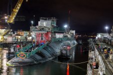
Back to the original subject, it looks like what they did with Tex is to use marker poles for alignment. In the background of some of the videos you can see a large (~8" diameter) vertical pole with braces welded to the dock floor. What they did was use 2 of these, one fwd and one aft, with the bases precisely measured off the block build such that when specific spots on the ship where up against the poles she would be in the right spot relative to the blocks.
It's also easier on her because the build is essentially all flat, so the tolerances are much greater - as long as the keel and docking keels land somewhere close to centered on the blocks it's good enough. IIRC if you pay close attention to some of videos you will see that either bow or stern is not centered on the keel blocks.
Up through the early 20th century, most docks had a row of flat keel blocks and ships were relatively narrow in profile, so all the really needed was keel support. So ships would be brought in, roughly centered in the dock so the keel landed on the blocks and then after landing side shores would be wedged in between the hull and the sides of the dock for stability, supplemented by bilge shores when the dock was pumped down. This is why older docks generally have stepped sides.

Because all you needed were flat keel blocks, exact location of the ship was not critical. As ships got bigger, additional blocks were needed, but generally still just flat blocks. Texas is a good example - docking keels are flat, and in fact carried fwd and aft below the curve of the hull to allow the use of flat blocks. The below picture of New York sinking shows this is good degree with 2 docking keel extensions fwd/aft on each side. The inboard set likely was original, and the outboards installed with the bulges.

In contrast, modern docking systems use blocks shaped to match the curves of the hull, which makes a much higher degree of precision necessary. In submarines for instance, the block build is very much a cradle, with the side blocks and fwd/aft end of the keel blocks being on the order of 2 ft higher than the keel line. Also, modern boats have lots of sensors, hull openings, fittings, etc. that need to be kept clear of the blocks, which also makes it very important to know exactly where the blocks go and where the ship lands.