Wheelin66bronco
Pure Blood
I found a few threads by arse_sidewards and the like, and a calculator posted by larboc
 engineersviewpoint.blogspot.com
But I'm not smart enough to put in the info to get what I need.
engineersviewpoint.blogspot.com
But I'm not smart enough to put in the info to get what I need.
Some assistance please.
It will span across shop, I want to set a I-beam for a rolling hoist.
It will be supported by vertical I-beams on the ends for which I poured extra deep spots into the floor to support it.
I'd like to see what the beam size would need to be for three different weight limits, and I can decide based on size, cost, and weight to get set via tractor bucket etc.
30' span
13' end legs(depending on beam width)
2,000, 4,000, 6,000, 8,000 capacity at center
Is square or tapered flange better?
Am I missing anything?
Example of rolling trolly:
 www.mcmaster.com
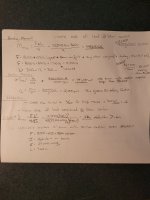
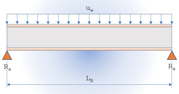
Beam Total Maximum Uniform Load & Reaction: ONLINE CALCULATOR
Designing a simple beam shear connection is easy and quite simple, of course. All that an engineer needs to do is to determine ...
engineersviewpoint.blogspot.com
Some assistance please.
It will span across shop, I want to set a I-beam for a rolling hoist.
It will be supported by vertical I-beams on the ends for which I poured extra deep spots into the floor to support it.
I'd like to see what the beam size would need to be for three different weight limits, and I can decide based on size, cost, and weight to get set via tractor bucket etc.
30' span
13' end legs(depending on beam width)
2,000, 4,000, 6,000, 8,000 capacity at center
Is square or tapered flange better?
Am I missing anything?
Example of rolling trolly:
McMaster-Carr
McMaster-Carr is the complete source for your plant with over 595,000 products. 98% of products ordered ship from stock and deliver same or next day.
www.mcmaster.com