What's new
  • Check out our new Group Buy Program! We're kicking it off with Baja Designs! $10 Flat rate shipping no matter how much you order!

Master Cylinder swap line question

Skinny

Well-known member
Joined
Feb 28, 2023
Member Number
6236
Messages
461
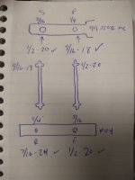
Long story short I'm trying to get a different MC on my S10 project. I'm using an MC from a 99 C3500 which is a Dorman M630028. It has a 1/4 line 9/16-18 fitting on the primary and a 3/16 line 1/2-20 on the secondary.

I am mating this to a PV4 Disc/Disc combination valve. It has a 1/2-20 on the primary and 7/26-24 on the secondary but it seems like the tube sizing is opposite.

Attached is a diagram of what I have for sizing. I can certainly make a set of stubs that will mate both ends to what sizes they are. But it seems like the size of the flare is made for the opposite size.

If I get an adapter to make the thread size work the tube size is off no matter what I do.

Should I just convert all fittings to AN and just have a pair or short stub lines made to eliminate this issue? Thoughts?
 

Attachments

  • IMG_20231130_175658763.jpg
    IMG_20231130_175658763.jpg
    1.3 MB · Views: 101
On the C3500 master cylinder, is the primary port closest to the booster?

I'm thinking maybe I F'd this up assuming it was and I'm backwards.
 
On the C3500 master cylinder, is the primary port closest to the booster?

I'm thinking maybe I F'd this up assuming it was and I'm backwards.
Waiting to see the answer, working the same issue on a Toyota.

Closest to the firewall is primary or front, is what i'm learning.
 
So that's what I always thought as a general rule of thumb. I could see on a disc/disc master where the reservoir is equal size for both circuits they may be the same size and interchangeable. I could see that but unaware if it's true.

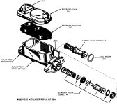
So the first image shows primary closest to the booster as we believe it to be.

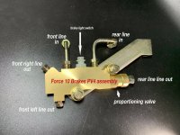
Second image shows the inlet identification on the combination valve. Seems like all the combo valves are plumbed this way regardless of internal valving.

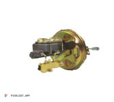
Third image shows preassembled brake kits. These completely contradict the plumbing layout of the first two images.

So I'm definitely lost on this one, thought I was smarter than this 🤣
 

Attachments

  • 0900c1528007c3cc.jpg
    0900c1528007c3cc.jpg
    125.3 KB · Views: 16
  • 2969425558.jpg
    2969425558.jpg
    527.4 KB · Views: 15
  • image_6483441_39_1024x1024.jpg
    image_6483441_39_1024x1024.jpg
    38.3 KB · Views: 18
Waiting to see the answer, working the same issue on a Toyota.

Closest to the firewall is primary or front, is what i'm learning.
So I'm at the shop now and if I reverse the lines I have set up they fit the big 1 ton MC from the C3500 truck.

So I'm assuming on this MC the primary and secondary are reversed. The flare on the casting also matches the size of the tubing if you reverse them.

So there must be some MCs that are what I consider normal and some that are reversed.

The stock MC on my S10 and one that I mocked up from an 89 R2500 Suburban (M1873 part number) is just like the S10. Both are quick takes and both are primary closer to the booster.

I think I'm going to use the Sub MC just because I already have it mocked up. We will see how good it works with 4 giant SuperDuty calipers.
 
So that's what I always thought as a general rule of thumb. I could see on a disc/disc master where the reservoir is equal size for both circuits they may be the same size and interchangeable. I could see that but unaware if it's true.

So the first image shows primary closest to the booster as we believe it to be.

Second image shows the inlet identification on the combination valve. Seems like all the combo valves are plumbed this way regardless of internal valving.

Third image shows preassembled brake kits. These completely contradict the plumbing layout of the first two images.

So I'm definitely lost on this one, thought I was smarter than this 🤣
So maybe with the block the proportioning is built into that and that master is equal front or rear and the block controls it.

Wild assed guess, because I'm clearly not smart enough. I'm trying to run dedicated lines completely separated and choke off the rears as needed with an adjustable valve.
 
I think with a disc/disc setup there is no proportioning built into the combination valve. So really the only gain is when there is a hydraulic failure it blocks that circuit and there is a switch to illuminate the BRAKE indicator on the dash.

So in theory what you are doing will work without that functionality.

In the C3500 MC either the circuits are equal or GM changed the locations for whatever reason. It makes perfect sense of I flip my combo valve around it fits fine other then the lines being too short.

This really sucks because I have no idea how it will stop with the Sub MC. I guess I'm going to run it. If I have aow pedal and not enough fluid then I have to go up a size in MC and know that I'll have to rework the lines a bit.

I'm just hoping that if I do have to go up that I have enough booster and don't get a rock hard pedal. The S10 already has a 7" dual diaphragm booster so the only next step there is hydro or an ibooster.
 
Top Back Refresh