What's new
  • Check out our new Group Buy Program! We're kicking it off with Baja Designs! $10 Flat rate shipping no matter how much you order!

Determining amperage for switch.

woods

I probably did it wrong.
Joined
May 22, 2020
Member Number
1120
Messages
5,162
Its on my motorcycle.

I've removed the need of a key. Right now, its two open wires. I twist them together, bike gets 100% power. I split them, bike gets cut off.

Essentially I'm looking to replace the ignition key with a simple switch.

How many amps does that switch need to be rated for? Bike's main fuse is 30A so I was going to use a 30A switch, but I have limited options for 30A switches.

Last night I jumped it with a 5A fuse to see if that would even hold, and the bike started, ran, idled, zero issue. So perhaps 30A is overkill?

I have a multimeter. There a setting I can switch to on it that will tell me how many amps I should have there? Using Ohm's law or something?

I know I can run a relay, but I would like to keep the wiring down to a minimum.

Explain this to me like you would explain this to a toddler. :flipoff2:
 
Get a standard 20amp toggle switch, you'll be A-OK

I have a multimeter. There a setting I can switch to on it that will tell me how many amps I should have there? Using Ohm's law or something?

Use the Ampmeter setting maybe ? :flipoff2:
Good to know : most multimeters have a max amp usable on the ampmeter function. 10amp seems pretty standard. They also usually have a dedicated plug to put the leads in for this function to work.
 
Get a standard 20amp toggle switch, you'll be A-OK


Use the Ampmeter setting maybe ? :flipoff2:
Good to know : most multimeters have a max amp usable on the ampmeter function. 10amp seems pretty standard. They also usually have a dedicated plug to put the leads in for this function to work.
And most people have already blown that 10amp fues inside their VOM and wonder why the amp reading doesn't work. LOL

I am sure 30 is for everything. Use a 20 amp, if it melts, well then you already know you can just twist the wires together to get you home.
 
And most people have already blown that 10amp fues inside their VOM and wonder why the amp reading doesn't work. LOL

I threw a couple extra fuses inside the meter housing from last time I had to change one.

Fuck ups happen but I like to be ready :laughing:
 
yea, I saw that 10A setting but I have it on the other.

I understand about 1% of 12v electrical. red is positive, black is negative. if its not sparking or melting, we're good.

My multimeter is about a hundred options. I can read mA and V on it. And that's about it. :laughing:
 
just put it on a relay.
tape a piece of wire to relay so if relay fails you can just jam wire into the relay socket to get power.
use whatever switch you fancy.
 

get a load tester if you really want to nerd out

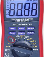
71Nzpqxm44L._AC_SL1500_.jpg


I've got that thing which I don't know what just about all those symbols do. I've got the wires plugged in just as they are in the picture. :laughing:
 
Measure the resistance (ohms). Set the meter to the red circled setting. Put one lead on each wire. Document the reading. example 4 ohms.
12 volts divided by 4 ohms = 3 amps. 5 amp or larger needed.

Ohm's law, google it. only requires 2 out of 3 things. Voltage, resistance and current. If you know 2 your can find the 3rd.
You know you have 12 volt (battery). Measure the circuit resistance.

Voltage divided by amps = resistance
Voltage divided by resistance = amps
Amps x resistance = voltage
 

Attachments

  • Screenshot 2021-12-21 124013.jpg
    Screenshot 2021-12-21 124013.jpg
    104.7 KB · Views: 22
It was 3 ohms. Can confirm. I thought 5A was waaaaaay too low that's why I was questioning myself. :homer:
 
10 -15 amp switch should work fine in that circuit. Lots of choices too.
 
ok. as usual, just over engineering the crap out of this. If they made something reasonable, I'd be putting a 100A unit in there. :laughing:
 
Yeah I was wondering about that. A knife switch even if it was 3 phase would work as it separates the contacts no?
 
The full output of the stator/alternator won't be running through the ignition switch. There's already some arrangement of relays depending on the bike.

What bike is it? I bet we can find a wiring diagram.

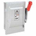
Either way I bet a standard 15-20 amp switch would be just fine. Get something waterproof. I looked around and found this one that happens to be 25A rated. I like Pico switches, they always work well for me.

PICO 5588PT Waterproof On-Off SPST Toggle Switch 1/2 Hole 2 6-16ga Leads 12V 25 Amp Amazon.com
 
Do you have a mechanical amp meter laying around, like out of a tractor or replacement that goes under the dash?
You could use that to measure amps.
 
Run a 30 amp relay and you can run any switch. Did you check the fuse box to see what the ign circuit amprage was? That will tell you.
 
Measure the resistance (ohms). Set the meter to the red circled setting. Put one lead on each wire. Document the reading. example 4 ohms.
12 volts divided by 4 ohms = 3 amps. 5 amp or larger needed.

Ohm's law, google it. only requires 2 out of 3 things. Voltage, resistance and current. If you know 2 your can find the 3rd.
You know you have 12 volt (battery). Measure the circuit resistance.

Voltage divided by amps = resistance
Voltage divided by resistance = amps
Amps x resistance = voltage
Above equations are correct for DC circuits.

For AC, you must factor in the Power Factor (PF), which is 1.0 for a purely resistive load. For an inductive load, for example an AC motor, the PF is usually about .8.
 
The only thing AC on a bike is coming from the alternator (or AC generator) to the rectifier. After the rectifier it is allDC.
That ign circuit is DC.
 
The only thing AC on a bike is coming from the alternator (or AC generator) to the rectifier. After the rectifier it is allDC.
That ign circuit is DC.
That's different than snowmobiles then. Most snowmobiles run A/C voltage for everything other than the starter.
 
That's different than snowmobiles then. Most snowmobiles run A/C voltage for everything other than the starter.
Voltage doesn't run. Voltage appears across. Current flows. Power is transmitted around the conductors.
 
I have this set up on my bike
the keyed ignition is there, nothing going to it.

The switch is there, just hidden
 
yea, I saw that 10A setting but I have it on the other.

I understand about 1% of 12v electrical. red is positive, black is negative. if its not sparking or melting, we're good.

My multimeter is about a hundred options. I can read mA and V on it. And that's about it. :laughing:
There is more to 12V electrical? I'm pretty sure that is all there is to it :laughing:
 
Top Back Refresh