What's new

Warm 5 pin remote to Albright Contactor Help

Kyle

Formerly known as Kyle_T
Joined
May 24, 2020
Member Number
1339
Messages
602
Loc
Fort Worth TEXAS USA
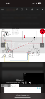
I’ve read through the threads and wired mine like this pic yet it won’t work. If I jump the contactor that works so how in the world is the warn remote wired? I can’t get anything to pin out on it. Ignore the dash switches I’m not doing that.

The colors on mine are the same as the pic too.
 

Attachments

  • IMG_5775.png
    IMG_5775.png
    106.2 KB · Views: 30
You must ground the terminal and the wire from the switch. I about broke my fucking neck trying to get that into runningproblems head.

Lets see some picks of your connections.
 
You must ground the terminal and the wire from the switch. I about broke my fucking neck trying to get that into runningproblems head.

Lets see some picks of your connections.
Which terminal?

Literally mine is exactly
Like that diagram.
 
Last edited:
That diagram is missing the ground wire to the controller. The black wire that runs to the plug in the image below. Or just wire the ground directly to the brown lead and you can use 3 or 5 pin controllers

1717695487627.png
 
That diagram is missing the ground wire to the controller. The black wire that runs to the plug in the image below. Or just wire the ground directly to the brown lead and you can use 3 or 5 pin controllers

1717695487627.png

Where does it ground to on the Albright? Mine is wired exactly like that pic too. Black winch controller ground on the ground lug on the winch
 
Are you running a 3 pin or 5 pin remote?

The 5 pin remotes have a second switch function on the ground side. The 3 pin remotes only control the directional control on the + side. (That's not always true. Some of the 3 pin directional control diagrams I've seen from Warn use the - side)

If you're running a 5 pin then the black wire that runs to your controller is connected by the switch in the remote to the brown lead on the albright. That works as a trigger wire like a normal relay function. The albright won't power unless it sees the - from the remote.

If you're using a 3 pin remote, that wiring diagram won't work. You would need to run the ground (black) directly to the brown wire on the albright which bypasses the switch in the remote completely. I run my albrights this way so I use can either 3 or 5 pin remote. I haven't tried the 6 pin remotes.

If this isn't your issue you need to post pics of your wiring.
 
5 pin.

I did exact what both digrams say.

Black to winch ground
Red to hot
White brown green left to right on the spade terminals.

I guess I don’t understand what the warn 5 wire accomplishes. With 5 wires

My remote is likely the “old” warm style because it’s a 2000 model Winch
 
Last edited:
Try tieing the brown lead on the Albright directly to ground.
 
Try tieing the brown lead on the Albright directly to ground.
No change. I’m trying to pin out the remote but I have zero clue how it functions to be honest.

Jumping the terminals the winch works so the solonoid is good
 

Attachments

  • IMG_5782.jpeg
    IMG_5782.jpeg
    1.7 MB · Views: 2
Last edited:
Maybe this is what I need to do
Here’s a warn connector wiring

IMG_5833.jpeg


From the back. Brown is top corresponding to the slot on the other side.


From this side brown is at the slot and white is clockwise one pin

IMG_5835.jpeg


I think both diagrams are the same just the wire colors are different.

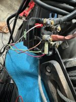
Here’s the contactor wiring.

IMG_5836.jpeg
 
I put my multimeter across the 3 terminal wires and all 3 have 12 volts when the switch is actuated regardless of which way. I pinned out the remote and it seemed to be correct. So I’m goofed on something.

I’ll double check it again tomorrow I don’t have any idea why it’s not working. Maybe my remote is broken.
 
You must ground the terminal and the wire from the switch. I about broke my fucking neck trying to get that into runningproblems head.

Let’s see some picks of your connections.
Yeah…I appreciate you sticking it out. Maybe I can explain it and help out someone with what I learned.
I put my multimeter across the 3 terminal wires and all 3 have 12 volts when the switch is actuated regardless of which way. I pinned out the remote and it seemed to be correct. So I’m goofed on something.

I’ll double check it again tomorrow I don’t have any idea why it’s not working. Maybe my remote is broken.
Co-Neckt the BROWN wire and the BLACK wire going to the motor ground on the solenoid. You are seeing 12v (+) everywhere because the loop for a current is not being completed.

The ground on the Albright is the middle.
1717730759911.jpeg


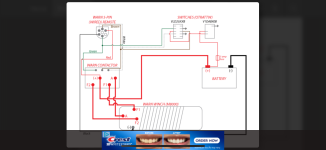
See how the Albright has wires from the 5pin switch AND the motor? (Not being an asshole) Electricity does this weird thing where it wants to make (+) and (-) meet up. So using the diagram above power flows through the circuit (Albright connector to the winch motor) when you connect Yellow and Black at the 5pin switch.
When this happens the Albright connector sends (+) to the Yellow wiring to the F2 post.


Edit: if you’re trying to do in cab winch controls you have to run a ground wire from (guess) the middle Albright post to the ground post on the switch you’re using to send (+) to your In/Out posts.
 
Yeah…I appreciate you sticking it out. Maybe I can explain it and help out someone with what I learned.

Co-Neckt the BROWN wire and the BLACK wire going to the motor ground on the solenoid. You are seeing 12v (+) everywhere because the loop for a current is not being completed.

The ground on the Albright is the middle.
1717730759911.jpeg


See how the Albright has wires from the 5pin switch AND the motor? (Not being an asshole) Electricity does this weird thing where it wants to make (+) and (-) meet up. So using the diagram above power flows through the circuit (Albright connector to the winch motor) when you connect Yellow and Black at the 5pin switch.
When this happens the Albright connector sends (+) to the Yellow wiring to the F2 post.


Edit: if you’re trying to do in cab winch controls you have to run a ground wire from (guess) the middle Albright post to the ground post on the switch you’re using to send (+) to your In/Out posts.
No in cab. I used the diagram I posted. I disconnected brown and hooked the ground to the Albright and the motor lug too and nothing happened but I’ll try it again.

So in this diagram brown is unused correct?

I’m wondering if my remote or something else is going on.
 
Last edited:
No in cab. I used the diagram I posted. I disconnected brown and hooked the ground to the Albright and the motor lug too and nothing happened but I’ll try it again.

So in this diagram brown is unused correct?

I’m wondering if my remote or something else is going on.
So you already have a ground wire from the in cab winch control momentary switch to the middle Albright post with the brown wire?
 
So you already have a ground wire from the in cab winch control momentary switch to the middle Albright post with the brown wire?
No in can just the warn wired remote.

Yes I jumped the brown to ground from the Albright connector. I’ll try it again tomorrow though.
 
No in can just the warn wired remote.

Yes I jumped the brown to ground from the Albright connector. I’ll try it again tomorrow though.

Maybe this helps. Fast forward about 20 minutes.
 
Well I’m thinking the actual switch is bad or there is a break in the wiring. Got it to work extending but won’t work reeling in. So my issue is buried in the handle it seems
 
Post pictures of all your wiring.

Wait: you could also try a momentary switch to check your wiring. An ON/OFF/ON would be easiest. An On/off would just require you change the wiring to test each direction.
 
Last edited:
Post pictures of all your wiring.

Wait: you could also try a momentary switch to check your wiring. An ON/OFF/ON would be easiest. An On/off would just require you change the wiring to test each direction.
Yeah the solonoid is good my remote is bad. The in function is dead.
 
Well I’m thinking the actual switch is bad or there is a break in the wiring. Got it to work extending but won’t work reeling in. So my issue is buried in the handle it seems
Switch the wires and it ahould spool in but not out.
 
Switch the wires and it ahould spool in but not out.
Yep that’s what I did. 25 years must be the lifespan. As soon as I started to mess with it the wiring insulation systems cracking off and flaking and exposing really tarnished conductor wires. So makes sense why 12v was at every pin there is a short in it somewhere.
 
Put a cheap $20 wireless on it. They work great. I never use my wired remote anymore.
 
Top Back Refresh