What's new

Slow Start of Fan

WMIF

Member
Joined
Dec 4, 2020
Member Number
3111
Messages
23
Hey all,
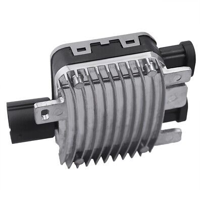
I have a couple salvaged high power fans from volvo s60 cars. They had a computer box directly attached that I assume was controlling the speed of the fan. My truck is obviously not a volvo, so the box went away. The fans operate great with just straight 12v. I got a temperature fan speed controller from amazon with 2 relays - low and high speed. I wired the fans in to run in series on the low setting, and then in parallel on the high setting.

Testing the fans on the bench went great and I saw about 25 amps from a single fan on full speed once it settles in. When in series, they collectively cruise about 20 amps. All within specs of the relays and fuses for the fan controller.

Once installed on my truck, I start popping fuses when it goes directly to the high setting (either using the AC/manual turn on wire, or if the temp is high enough when turning the key on). I mean POP too. Get a meter on it, and I see a single fan pull about 100 amps while starting. Duh. My bench power supply was limiting current, so I didn't get the inrush to start them. My group 65 odyssey on the other hand is happy to give it all.

Finally the question:
Is there some already built standalone device that I can wire into the high side to limit the current during this startup?
 
What's this drawing power from and what size fuse are you using for it? Are there fuses in the speed controller?
 
The controller is connected to a keyed source with a 5 amp fuse. Each of the relays are connected to the battery through a 40 amp fuse. Normal start on slow speed ( fans in series ) and everything is perfect.
 
Sounds like a higher capacity fuse to accommodate the inrush current to the motors is needed, if I'm picturing the schematic correctly. Are the 40 amps fuses on the leads to the motors or the relay coils?
 
You want a PWM fan controller. Should be a recent topic I believe diode dynamics has one I remember reading about it here not the other place.
 
I thought Diode Dynamics was exclusively lighting. I'm bench running Dart Controls PWM controllers now. They're kinda pricey.
 
I thought Diode Dynamics was exclusively lighting. I'm bench running Dart Controls PWM controllers now. They're kinda pricey.
Here’s the thread I remember.

 
Here’s the thread I remember.

Damn good read. Only speed controller I saw on there was this - constant temperature controllers I'm guessing they're 12-volt only.
 
I'd like a soft start capacitor or something that works like that for my shitbox, just something to slow the inrush or drag on the alt and batt when it's commanded on.
 
you can try use a fusible link first. they will not blow right away, but will blow if the draw is too high continuously.
 
That’s what I was hoping for. It’s not a regular occurrence since my controller is two speed. It’s only if I turn the truck back on too close to turning it off where the heat hasn’t had a chance to dissipate yet, causing the controller to trigger high speed immediately.

I've got a a 400-500% inrush that tapers for maybe 10 seconds until it settles. Might work with one of those breakers mentioned in the big thread linked above.
 
change the kind of fuse you're using.
I assume you're using ATC style blade fuses for this? They are instant blow fuses.

mcase/jcase fuses like the ones you see the OEMs use for high current underhood shit are slow blow fuses and will handle the inrush.


Thanks for that 87manche . I see some MCASE fuses on amazon listed as slow blow and others that don't indicate. Is that a standard feature? What is the multiple of current it can take on? Can't seem to find that info yet.
 
some are, some aren't, some have longer time delays.
this pdf from littlefuse lays out most of it.

but generally 4-6 seconds before they pop at double the fuse rating.
 

Attachments

  • fast-fuses-versus-slow-how-do-you-choose.pdf
    184.1 KB · Views: 40
it's PWM, so technically you'd have to chop it up like the volvo ecu sends it. not sure if can bus or not.

There is a P2 volvo in my driveway and I have all the documentation in VIDA.
I'll look and see if I can figure out the specifics.
maybe just hook the o scope to the control wire and have a look.

the easy button would be the derale controller if you're looking for true variable speed fan shit.
That would be super cool of you if you could find the time to do that.

I'll send you a sticker:flipoff2:

junkyard parts are friggin cheap, often aftermarket stuff is just cheaply made.
 
so an arduino uno for full temperature control and logic and a volvo junkyard fan controller full of mosfets?

I like it.
 
so an arduino uno for full temperature control and logic and a volvo junkyard fan controller full of mosfets?

I like it.
No that sounds too complex, those temp senders send a varying voltage depending on temp right? Hook that shit right to the fan controller, but I may be imagining it as more simple than it is.
 
so an arduino uno for full temperature control and logic and a volvo junkyard fan controller full of mosfets?

I like it.
I started some work on building this on a board, but those mosfets to handle this kind of load are not easy to figure out, or keep cool. Water sensor to cut power if fording water high enough. AC and override to spin fan up. Timer after key off. If that $20 volvo box will take the heat, arduino could do a lot of cool things.
 
No that sounds too complex, those temp senders send a varying voltage depending on temp right? Hook that shit right to the fan controller, but I may be imagining it as more simple than it is.
it don't think it works like that.
I'll look in the volvo documentation, but if it works like anything else PWM controlled, it's about how many milliseconds the pulses are, not really the voltage.
longer 5v pulses just happen to read higher on a multimeter.

don't fear the arduino, that shits super simple.

depending on how the pwm works out, maybe a simple servo tester like circuit, with a timer that just reacts to a pot, but then it's not all automagic, and I really think that's what you're after.

I'll look in VIDA at the wiring diagrams tonight. I've got to replace the thermostat housing this weekend anyhow, so I'll have a poke at the fan controller box with a meter.

I'll say that it must be reliable as shit, because I've never really seen anyone posting threads about how to make it work again.
 
so this is what VIDA has to say about the design of the cooling fan control module
you'll have to live with a screen shot because I don't have my virtual machine setup for clipboard access to my host.

but anyway it seems I can just activate it whenever I want, and I imagine that it's 25/50/75/100 output levels are doing exactly what you do with relays, just running them in series or parallel.
So it's as simple as sticking a scope onto the PWM input, commanding fan speeds in VIDA, measuring the pulse width and emulating it to the controller with a standalone box, either with manual inputs or some sort of temperature control.

personally I'd do temperature control with an arduino doing everything.
it could even be safely mounted in the cab, you just need a remote temp sensor and a single wire to the fan controller.
 

Attachments

  • Screenshot from 2021-04-26 19-59-59.png
    Screenshot from 2021-04-26 19-59-59.png
    171.3 KB · Views: 68
I started some work on building this on a board, but those mosfets to handle this kind of load are not easy to figure out, or keep cool. Water sensor to cut power if fording water high enough. AC and override to spin fan up. Timer after key off. If that $20 volvo box will take the heat, arduino could do a lot of cool things.
I feel like if we used the junkyard volvo fan controller for the high current stuff, then this becomes something really simple to make an arduino control.

which also makes me wonder just how adaptable the volvo fan controller might be as a giant solid state relay setup for any arduino electric project.
you'd need to fan cool it, it's designed to sit in the airflow from the big ass cooling fan.
 
I'm not sure that actually fixes the fuse blowing or inrush current though if I'm honest. I'm pretty sure that the fan controller is just some fancy relays in a box.

here's what the signals page says about it. so 100hz, maybe it is a full on PWM solid state relay that we can use to limit load.
Untitled.png
 
Last edited:
I'm not sure that actually fixes the fuse blowing or inrush current though if I'm honest. I'm pretty sure that the fan controller is just some fancy relays in a box.

here's what the signals page says about it. so 100hz, maybe it is a full on PWM solid state relay that we can use to limit load.
Untitled.png
It will fix the inrush if the controller accommodates for it. Slowly ramp speed up from a cold start regardless of temperature reading.
 
It will fix the inrush if the controller accommodates for it. Slowly ramp speed up from a cold start regardless of temperature reading.
yes, assuming that's how it actually works.
I guess I need to buy one on ebay so we can see before I take apart my wife's daily driver and break it.
:laughing:

I do have a couple arduino unos kicking around in a box somewhere.
 
it don't think it works like that.
I'll look in the volvo documentation, but if it works like anything else PWM controlled, it's about how many milliseconds the pulses are, not really the voltage.
longer 5v pulses just happen to read higher on a multimeter.

don't fear the arduino, that shits super simple.

depending on how the pwm works out, maybe a simple servo tester like circuit, with a timer that just reacts to a pot, but then it's not all automagic, and I really think that's what you're after.

I'll look in VIDA at the wiring diagrams tonight. I've got to replace the thermostat housing this weekend anyhow, so I'll have a poke at the fan controller box with a meter.

I'll say that it must be reliable as shit, because I've never really seen anyone posting threads about how to make it work again.
So the ecm is getting a reference signal from the sender then converting that to pwm signal to the controller, Hoped volvo put the pwm in the controller.

I don't fear aurdino, just haven't found the basics dumbed down enough for me to read and understand. back in 01 when I was fingering out excel, a higher up gave me the rundown on macros and I was able to complete the sheets I was working on.
 
I didn't read the whole thread but I've successfully wired my fair share of Volvo fans.

If you use the 2sp Volvo relay that's meant for this fan, a 8ga wire from battery to power it and a 40amp MEGA fuse (important), you'll be fine.

Use an ECM command or a dual temp switch that goes in your coolant system to trigger each of the speeds.
 
So the ecm is getting a reference signal from the sender then converting that to pwm signal to the controller, Hoped volvo put the pwm in the controller.

I don't fear aurdino, just haven't found the basics dumbed down enough for me to read and understand. back in 01 when I was fingering out excel, a higher up gave me the rundown on macros and I was able to complete the sheets I was working on.
yes, that's the assumption from the VIDA documentation.

Until I put a scope on it it's just my assumption.

So you can either use an ECM to trigger it, or you can build a little arduino box to trigger it based on a temp sender's resistance.
The code is literally
If the ohms are (x) then output (x) on the PWM circuit, but never apply more than (x) to the PWM circuit in (y) amount of time.
in a nutshell obviously.
and that assumes that the controller is actually a PWM controller for the fans, and not just some relays in a box with a circuit board that controls them based on the PWM input it sees just because it was cheaper to make than relays and wires.


There are tutorials for pretty much anything you'd ever want to do.

and most of the common sensors and such have predefined libraries that just make them work. It's not until you try and do something no one else has documented that you get off ito the real weeds of building circuits and shit. most of it is plug and play. There will be some transistors/resistors involved in plugging an arduino into the cars 12V. It's meant to do 5V things.

like I said, I need to ebay/junkyard one so that I can plug it in with a bench power supply and see how it operates and how we control it, and if it's even worth using for the trouble to do so.
 
Top Back Refresh