What's new

Project Glacier Cold Beer - a '67 Jeepster Commando

I don't know how many soft tops were on this jeep, but about 110 holes filled later... ground smooth...

Working the rockers now.

20201229_111009.jpg


20201229_111243.jpg
 
I debated for a long while on the rockers. I liked the look / reveal of the factory rockers, but didn't like the ground clearance. There are kits to plate them out there, and initially I'd prepared the passenger side for 2x4x.120 box tube.

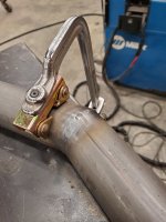
As discussed previously, I was concerned about the 18ga body creasing above the re-enforced rocker.

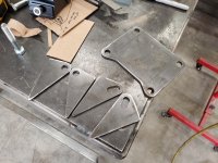
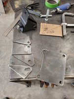
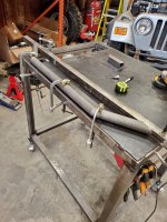
After some inspiration from Len Barron in a Facebook group for jeepster commando club of America, where he had welded angle iron to the lower flange, I adopted that and came up with this to re-make the factory rocker in 18ga, gain 2" in clearance keep the strength (that is the only part of the car that holds the door opening true), and keep it looking the way I want.

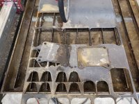
I went to Those Guys Rod and Customs in Bremerton, WA with my template piece, coors box notes, and negotiated (traded Coors Light) some time using the stop shear and 48" brake.

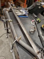
Unfortunately the piece i needed was about 57" long, so I needed to make the 48" piece then a smaller "extension", with a welded seam.

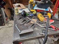
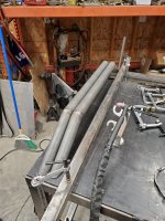
I'm pleased with the fit up, quick snack and some WI-FI time, and back to the shop to make it permanent, then replicate on the drivers side.

20201229_121008.jpg


20201229_121139.jpg


20201229_130529.jpg


20201229_121501.jpg
 
Looking sharp! Do you still have a piece of the cut-off body feature to hold up next to the new for comparison? If you dare?
 
Retaining the stock lines while making everything fit and look clean takes skill. Keep up the good work!
 
Cut some holes in the dash, got the top back on to figure out some on the cage.

When I went to take the top off, I'd made a crappy support structure from 2x4's and slings, and all the weight shifted in the webbing, so it was kind of a controlled fall to the floor.

Going back on, i cut some angle iron to bolt to the factory bedside rail holes (prevents the slipping) and fashioned up this strongback from some 2x2x.120 and some left over tabs. I cut up an old winch rope and tie bowlines in it, off fixed length, which then attach to the stringback. My first attempt at rigging was using the center tab on the 2x2, but the center point allowed the weight to shift. Threw the webbing on there, and was much more successful. Looking at it now, I should have seen that right off.

Anyhow, safely back on the car.

20201231_135933.jpg


20210103_181047.jpg


20210103_174413.jpg
 
Last edited:
Spent too much time messing around with my crappy notcher, but did get the SWAG reach-around to work on my Strong Hand Tube Notcher. the notcher uses 10mm hardware compared to the JD2 Notchmaster's 3/8, so the slot is just a C hair too small for the 10mm bolts. I drilled and tapped 2 more holes in the shaft support block to 3/8-24, to use the supplied bolts. The Strong Hand notcher uses a 13mm shoulder bolt for the pivot, compared to the JD2's 1/2" bolt, so just barely the wrong size again, but you have to drill your own hole for the Reach Around anyhow, so, #somebitchoughttadig

For some reason I didn't take any photos (will have to next time I'm in the shop) but I ripped off the buildco tools guillotine work holder and made a -not quite as good- version with my Longmuir plasma table.

Anyhow, my buddy Justin came over and we cut some 3/16" cage feet plates and made the drivers side A to C piece and B pillar. Took most of the day for the two of us to remember how to make tube end where we wanted it. Only had to use the pickup truck receiver hitch to 'unbend' a few degrees on one of the 2 bends. Seems we both do this just often enough to forget how to do it in between.

The other side and spreaders should go much easier, and part way through, should be able to pull the top which will make welding much easier.

20210110_162842.jpg


20210109_095811.jpg


20210109_095538.jpg
 
Got distracted by lots of other projects, including a full suspension and brake overhaul on the toy hauler. And snowmobile season.

Got the top of, don't like the straight b pillar, going to re make that.

Started cutting out floor rust in the passenger floor board.

Threw some shocks at it.

More pics tomorrow.

20210224_180518.jpg


20210224_180720.jpg
 
Got distracted. hopefully the lifter tick is gone in the buggy and then back on this build.
More distractions...

Lifters were fine. Swapped engines to one from a parts yard, had transmission gone through, same noise. loaded it up, wen to Sand Hollow in May.. 1 quart of motor honey in there..
Tore the flex plate in half... that was the noise. Got a new flex plate in Cedar City, swapped them in camp, drilled my own holes for the torque converter a little off. 2 days of wheeling and the transmission input bushing spun, and started pouring fluid out the front.

Trans out, rebuilt again (new pump housing too), another flex plate, drilled better, and back to wheeling the buggy.

Also took about 4 weeks of weekends to strip and re-deck my deck and do some work to a buddy's tacoma.
 

Attachments

  • 20210512_171508.jpg
    20210512_171508.jpg
    1.8 MB · Views: 86
  • 20210414_183623.jpg
    20210414_183623.jpg
    4.3 MB · Views: 73
  • 20210609_192555.jpg
    20210609_192555.jpg
    1.7 MB · Views: 77
  • 20210619_195236.jpg
    20210619_195236.jpg
    5.1 MB · Views: 80
  • 20210708_180931.jpg
    20210708_180931.jpg
    8.8 MB · Views: 89
Anyhow, some progress-

I ordered an LV3/6L80E package from lsswap.parts in October 2020, and was told a 6-8week lead time. Paid in full at that time. Called at 8 weeks and was told a 10 to 12 week lead time. Lots of missed promises, an almost loss in faith that I would see my parts ever, weekly phone calls to them became twice a week. Finally arrived in April 2021.

Started it on the pallet with a battery and the fuel pump in an old pot full of gas, seems to run. No instructions, no wiring chart, no connectors labeled... and it all appears to be butt crimp connectors and electrical tape, so we'll see how much I end up reworking.

Had a STaK 300 I bought a bunch of years ago, so ordered up the Novak adapter for the 6L80E to d300, which includes the right input shaft.
 

Attachments

  • 20210422_201348.jpg
    20210422_201348.jpg
    2 MB · Views: 63
  • 20210422_201354.jpg
    20210422_201354.jpg
    1.9 MB · Views: 59
  • 20210709_150836.jpg
    20210709_150836.jpg
    7.5 MB · Views: 58
The D300 was purchased sight un-seen, and then tossed on a shelf for the past 4 or so years. had a 4:1 gearset and 32 spline outputs, which I verified on receipt, but otherwise didn't look to hard at it..

Went to swap the input shaft on the 300. Had to drill out the t27 torx bolts to get it out.

Pulled the input housing out, and the gear stayed in the case. Missing the snap ring on the input shaft... that and the rust on the input shaft had me investigate more. Full tear down mode...

Apparently this case had gotten water in it at some point, which sat on the gears, and ruined the contact surfaces on the teeth. The rear output bearings weren't all the way pressed on, and there were no interlock pills, and I doubt the front output and rear output end play were in spec...

I guess I'll be putting some factory gears I have lying around in this case, and inspect the shafts and bearings really well, then get the drivetrain all together and roughly located... to start on drivetrain mounts.
 

Attachments

  • 20210711_203211.jpg
    20210711_203211.jpg
    8.1 MB · Views: 44
  • 20210711_203216.jpg
    20210711_203216.jpg
    7.3 MB · Views: 42
  • 20210711_205834.jpg
    20210711_205834.jpg
    7.8 MB · Views: 45
  • 20210711_205839.jpg
    20210711_205839.jpg
    3.7 MB · Views: 46
  • 20210711_205849.jpg
    20210711_205849.jpg
    1.8 MB · Views: 40
Last edited:
9" 3rd mem

Got distracted by lots of other projects, including a full suspension and brake overhaul on the toy hauler. And snowmobile season.

Got the top of, don't like the straight b pillar, going to re make that.

Started cutting out floor rust in the passenger floor board.

Threw some shocks at it.

More pics tomorrow.

20210224_180518.jpg

mmmmaybe tilt it at the same angle as the door seam?
 
I'd look at laying the B back to match the line up the rear of the door opening, it'd flow well I think.

mmmmaybe tilt it at the same angle as the door seam?
Agreed gents.

That's the plan. And a little crown in the b-pillar spreader because there is a smidgen of space under the hard top I can stuff it into, and if I get or make a soft top, that would help it drain. Of course, I need to put the top back on to do that, to make sure I don't over estimate the smidgen.
 
D300 back together with proper shaft end play, all the snap rings, and a 32 spline input. still sad about how hammered the STaK 300 is. Oh well, it ought to work just fine.

Mounted to the 6l80e with a Novak-Adapt piece. Nice piece, with integrated transmission mount. Maybe swing the drive train into the frame rails tomorrow.

Maybe.
 

Attachments

  • 20210820_094003.jpg
    20210820_094003.jpg
    7.8 MB · Views: 41
  • 20210820_122137.jpg
    20210820_122137.jpg
    1.9 MB · Views: 41
  • 20210820_122146.jpg
    20210820_122146.jpg
    1.8 MB · Views: 39
Went to cut some motor mount plates on the plasma table. About half way through cutting the 3rd one, I thought to myself... whoops, only needed two... oh well.

Stabbed the drive train in. Spent like 2 hours adjusting crank centerline up and down, side to side. Offset the whole package about 1" to the drivers side, about 5.5 degrees rotated up in the front.

Driveshaft looks viable with the low pinion 9" front, may end up a two piece with the suspension plans though. Exhaust looks almost impossible with the factory manifolds. Might try to cut and weld the cast to change the down pipe flange angle and see if it might squeak by.

Anyway, engine located, need to build some mounts, then get started on suspension.
 

Attachments

  • 20210906_085002.jpg
    20210906_085002.jpg
    8.7 MB · Views: 71
  • 20210906_090549.jpg
    20210906_090549.jpg
    7.1 MB · Views: 76
  • 20210906_172441.jpg
    20210906_172441.jpg
    3.9 MB · Views: 64
  • 20210906_172553.jpg
    20210906_172553.jpg
    1.9 MB · Views: 66
  • 20210906_172655.jpg
    20210906_172655.jpg
    3.9 MB · Views: 84
Love following along with this one. We appear to be at similar phases of build!

Love what you did with the rocker panels. I'm looking at doing something similar when I get to that point. Keep up the awesome work.
 
Motor mounts today. Drivers side has the fixed bolt, because that is loaded under throttle. The passenger side has a slot to make it easy to align, which is oriented "flat" when installed, which should make alignment of the drivetrain easier.

I intended to use XJ/TJ/MJ motor mounts, because they can easily be removed, (2 bolts into the frame side, 1 into the motor side), which, when removed, allows the engine to come forward and off the transmission if needed before it has to come up. When I built my buggy, I had to remove the block side mounts to pull the engine, and it's a total pain in the dick.

Factory xj rubber motor mounts don't exactly fit - the upper link on the passenger side and the steering column on the drivers side interfere with where the frame side mount would go. Have a line on some brown Dog mounts I'll pick up tomorrow, and cut apart for more clearance.
 

Attachments

  • 20210911_123532.jpg
    20210911_123532.jpg
    7.6 MB · Views: 35
  • 20210911_123553.jpg
    20210911_123553.jpg
    2.1 MB · Views: 32
  • 20210911_145520.jpg
    20210911_145520.jpg
    3.9 MB · Views: 35
Remade the drivers side plate to lower the mount under the steering column. A quick piece of 2x4x.120 with the end lopped of at a 45, with some holes to mount an XJ rubber mount. Passenger side is a 2x2x.120 box with some 11ga plate gussets. For the passenger side, I cut up a brown Dog 1" lift motor mount and made what would probably be a 1" drop mount, which gave me more clearance for the upper link.


Got enough in and welded to pull the crane out of the way.
 

Attachments

  • 20210918_083551.jpg
    20210918_083551.jpg
    2.1 MB · Views: 54
  • 20210918_083542.jpg
    20210918_083542.jpg
    1.9 MB · Views: 54
  • 20210917_111239.jpg
    20210917_111239.jpg
    3.5 MB · Views: 52
  • 20210917_105640.jpg
    20210917_105640.jpg
    2.2 MB · Views: 50
Last edited:
Started on the sub frame. I've not done much GTAW on round parts, so I figured an open root, not purged, round section would be a good choice. Came out okay.


The 1.5x1.5 in these photos is just a straight edge to align things.
 

Attachments

  • 20210918_112249.jpg
    20210918_112249.jpg
    1.9 MB · Views: 49
  • 20210918_140047.jpg
    20210918_140047.jpg
    2 MB · Views: 48
  • 20210918_140118.jpg
    20210918_140118.jpg
    1.8 MB · Views: 44
  • 20210918_145624.jpg
    20210918_145624.jpg
    2.1 MB · Views: 52
Top Back Refresh