ANGRYBLACK
Red Skull Member
The Neighbors are cool. We have no next door neighbors and the local county engineering dept behind us. It's a gearhead neighborhood with a bit of every discipline. Plus local LE loves me.
Follow along with the video below to see how to install our site as a web app on your home screen.
Note: This feature may not be available in some browsers.

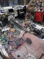
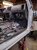
Slow progress because I'm cheap. I took 2 hinges, some scrap flat bar and a plexi door to make a mount for the gauges and shift indicator. When it's flipped down my boots don't get in the way. In the up position this will be part of the underdash hush panels. I plan to make those from FRP. Not bad for an afternoon of fumbling around catching up on Sick Week and endless KOH content.
Most G body hush panels were only installed on Grand Prix SJ cars with pillow top seats and a few T type regals. I'd like to have some OEM panels though. I haven't seen one in person in over 15 years. So FRP with some damping material it will be.
We have a rain storm tonight so after I clean the shop I will mock up the driver's seat to verify shifter placement for us both.
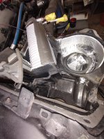
I also swapped out the 2 stage stock brake master cylinder for a 1" bore S10 unit. I'm gonna be solo for the rest of the build after May because the wife is moving back to Georgia to be close to the grandson's and career growth.
I'm gonna act like I'm a 20 year old me and probably move the bed into the shop to get the car moving under its own power for Drag Week 2023.
Or sleep on the creeper! I was so happy when reclining bucket seats became universalWe used to keep the coffee pot going nonstop and skip the bed. Got kind of loopy towards the end of the last minute build

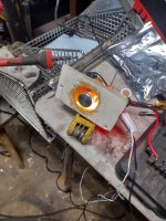
 I had some 1 1/2' X 2 1/2" 0.120 wall rectangle tube so i used that. I also have some oval 0.095 wall tubing of the same size but i didn't go that route because i had felt i could get more weld contact with the rectangle and the Oval tube is thinner than the arm material. I reused the ball joint pocket and tacked all it in after i rechecked the non favorable kingpin/ Steering inclination angle of the steering arms.
 . I could get 74 degrees with a thinner wheel and tire or a stock car style sway bar and a small notch of the factory frame.I'm so glad the next one gets the tube frame without care of going drag racing. Onto the rest of it.
 Now creeping forward for 2 hours in traffic surrounded by trucks cars and transit busses on a hot summer day at the Helix of the Lincoln Tunnel, all the while i listen to 1010 WinS news radio repeat the delay every 12 mins making me giggle. Then 45 mins in the tunnel just to get out, then the bumper to bumper traffic to get where i'm going will require to get the heat out. Hell the trip back from seeing friends will wind the car up on the Van Wyck expressway by the airport where one can sit still for 15 mins only to creep 50 feet forward. Yeah, school bus
 . getting stuck behind one on a planned route isn't the problem. It's the normal type of traffic this car will see day in and day out. Friendly banter aside.
I love this shit.
I always enjoyed your threads on the old place. But wow. This is on another level.
Thank youthat's some serious packaging accomplished there. hat's off to you!
My other junk is still around. Just sitting waiting to be continued.....It just been proven to function. This one gets done and finalized because bits and pieces of it have been done before. Over about 30 of them that I've played with. Well except the LS stuff. But life has proven to me that my 632 goes into the cab truck where fuel milage will never be a concern. And well there needs to be one in the house and at least least one in the driveway. "There should be a Bowtie Emoji" I have to source a column switch and the proper non cruise delay wiper stalk for the column, S-10, G body, F body or B body floor shift column to get the outer housing. Basically 4-5 columns to make what i need. The local pull a part is 2 hours away so its a weekend trip. Anyways