What's new

converting a 3 ph generator over to single ph

Clb

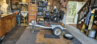
another toyota from P.R.K
Joined
May 19, 2020
Member Number
32
Messages
3,832
Loc
First 50 club
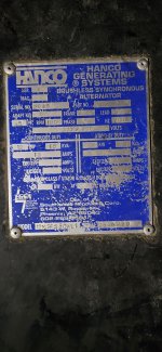
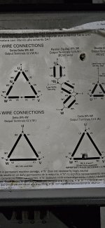
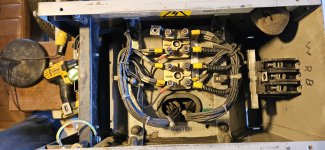
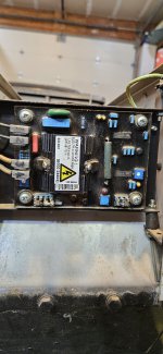
working onna 12 lead head
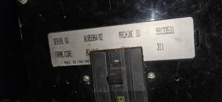
12 kw
15 kva
18 amps
60 hz
277 480volt
3 cyl Isuzu diesel prime mover @ 1800 rpm

pics to follow

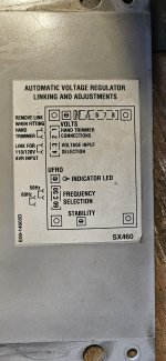
I can handle the rewiring part my problem is i do not know enough to be dangerous on this .
I can wire up a house or automobile, BUTTTT
.
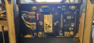
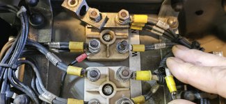
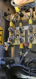
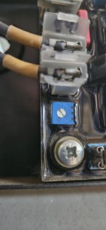
I have cleaned up the corrosion and noloxed the terminals and pulled an as built on the wiring so far..
So hold my hand?
:emb:
Eta
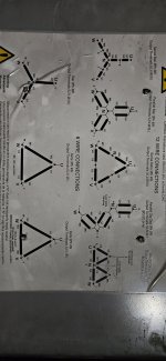
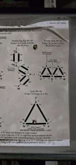
There's a lot of opinions on zig zag versus D.D.

How do I identify the coils from outside the cabinet?
 
Last edited:
Here's a start.
 

Attachments

  • 20240211_155113.jpg
    20240211_155113.jpg
    1.9 MB · Views: 28
  • 20240207_095423.jpg
    20240207_095423.jpg
    2.2 MB · Views: 36
  • 20240207_095610.jpg
    20240207_095610.jpg
    1.2 MB · Views: 39
  • 20240207_095600.jpg
    20240207_095600.jpg
    1.4 MB · Views: 30
  • 20240207_095555.jpg
    20240207_095555.jpg
    1.3 MB · Views: 25
  • 20240207_095924.jpg
    20240207_095924.jpg
    1.4 MB · Views: 22
  • 20240207_095758.jpg
    20240207_095758.jpg
    1.3 MB · Views: 20
  • 20240211_155010.jpg
    20240211_155010.jpg
    2.4 MB · Views: 22
  • 20240211_155025.jpg
    20240211_155025.jpg
    2.8 MB · Views: 26
  • 20240211_155039.jpg
    20240211_155039.jpg
    2.8 MB · Views: 28
Here's the current version.
Each pair has 2 sets of codes ex n has v6 and t 11 paired
along with w6 t12
and u6 t10
20240211_173758.jpg
 
Is the T wire for the Trimmer line? If it is then I’d say it is wired to match the top left diagram.
Series Star 3Ph 4W.
Output Terminals (U.V.W.N.).

The W5/W2/W1/Breaker is written backwards compared to the diagram.
V2/V5/V1 has the 2 and 5 backwards as well in the drawing.

If this is true then what you have marked as 7 is actually 6.
 
Thanks,
As to the T wire... I'm going to try and find out...

I pulled tag information off each wire. I could be wrong .
I will go over the cheat sheet and chime in shortly .
Then I'll have questions.
Fwiw This was in operation of a 900' Deepwater well by stead Airport so it was working as wired.
Did I mess up the diagram???
Maybe
 
The take off is labeled correctly.
The w5 w2 w1 bar is this with the wire lifted off going to bkr
The left lug had 1 wire labeled w5/t9
One w2/t6
And a solo black #7
Right lug has w1/t3 and one to bkr

The eyelets have 2 wires each.
 

Attachments

  • 20240215_090238.jpg
    20240215_090238.jpg
    1.4 MB · Views: 10
  • 20240215_090314.jpg
    20240215_090314.jpg
    1.5 MB · Views: 9
Last edited:
It might help if you make your drawing match the series star 3 phase one. I am not electrically inclined. I’m not an electrician. I’m just looking at letters and pictures.


Your N is wired one way. You have all the parts labeled. Make the wiring match the Double a delta single phase.

N gets U2, U5, V2, W1.
W gets U6 W5 and the 7 wire.
U gets U1, V6 and the 8 wire.

Connect V5 and W2.
Connect V1 and W6.
These two must just connect to each other. Since it doesn’t say C on the diagram I’m assuming they don’t get connected to C.

V should have nothing connected to it.


This should work, but I’ve never done it, I don’t work on generators, and I’m a well documented idiot. All I see are letters and numbers needing to connect to each other. I don’t know what the diagram is actually telling you. Heck….i don’t even see an outlet to plug anything into.

I have no clue what the difference between parallel and zig zag are, and it doesn’t matter if one works. I see one gets you HC4. I don’t know what that is. So if this burns your house to the ground I’m really sorry.
 
The take off is as built.
I don't know what I am doing much.
I'll look over the rest of what you wrote in the am.
As to burning the joint down...
:laughing:
 
Well I got an invite to go fishing, I'm setting on the lake.
I'll need to get back to this later...
:beer:
Ok time to start thinking :flipoff2:
 
Last edited:
It might help if you make your drawing match the series star 3 phase one. I am not electrically inclined. I’m not an electrician. I’m just looking at letters and pictures.
Eta this take off is as built.
Meaning that it's how it came out of service
Your N is wired one way. You have all the parts labeled. Make the wiring match the Double a delta single phase.
Ok . Not being a smart azz but how ? The unmarked side of n ( for example) goes back inside the head acting as a junction block ? Right?
The side labled ( again n for example) the goes both to the head and output breaker
N gets U2, U5, V2, W1.2
W gets U6 W5 and the 7 wire.
U gets U1, V6 and the 8 wire.

Connect V5 and W2.
Connect V1 and W6.
These two must just connect to each other. Since it doesn’t say C on the diagram I’m assuming they don’t get connected to C.

V should have nothing connected to it.
Which side of the coil is what I don't get/ know the difference between.
This should work, but I’ve never done it, I don’t work on generators, and I’m a well documented idiot.
I'm just knowledgeable nuff to be dangerous myself, so don't worry.
All I see are letters and numbers needing to connect to each other. I don’t know what the diagram is actually telling you. Heck….i don’t even see an outlet to plug anything into.
The back side of the bkr has output lugs.
I have no clue what the difference between parallel and zig zag are, and it doesn’t matter if one works. I see one gets you HC4. I don’t know what that is. So if this burns your house to the ground I’m really sorry.
:lmao:
 
Post up some photos of your wiring. I guess it wasn’t too hard if the two of use fingered it out.
 
Post# 13 above,
This is 2 -121.3v legs
1@ U
1@W
Using the double delta configuration
Not positive that we fixed it up but static testing is positive.
Thanxbud
 
Last edited:
I did have to adjust the trimmer pot on the avr( automatic voltage regulator) lil blue guy lower left.
The head was making 50v after the swap...
 

Attachments

  • 20240225_143835.jpg
    20240225_143835.jpg
    1.5 MB · Views: 6
  • 20240220_103433.jpg
    20240220_103433.jpg
    1.5 MB · Views: 6
50 volts seems a little low for American expectations.

Glad I could help out. I just happened to find the right link e planning what I’d try to talk through myself. I never knew double delta existed and I’ve never touched three phase stuff.

How did you know to mess with that pot trimmer thingy?
 
The difference between single phase and 3 phase is apparently why there is a trimmer.
I had help on that one.

Thank again.

Still waiting on the chimerican vendors for the breakers and cordage .
 
Did your Chimerican Vendor pets show up yet?

Was adjusting the trimmer pot as simple as adjusting the dial and checking voltage?
What is the highest output voltage you can get on single phase? 240?
 
Yes, it's all buttoned up.
Once we figured out the trimmers existence it was just turn the tiny flathead clockwise to desired voltage.


The configuration of the leads affect the output and thus the trimmer is needed to alter the output.

It took me advancing the dial about twice it's as built setting, about 2/3 of dial capacity.

I stopped at the range I needed which got 242.6 on governors low run speed.

So I would chance a guess it would probably be capable of 208 single phase wired this way, but didn't verify this....
 
Top Back Refresh