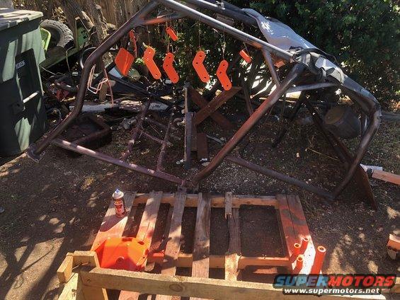
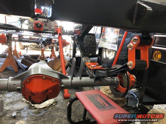
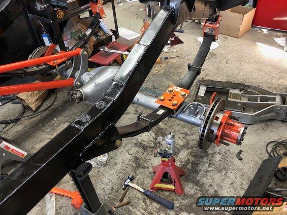
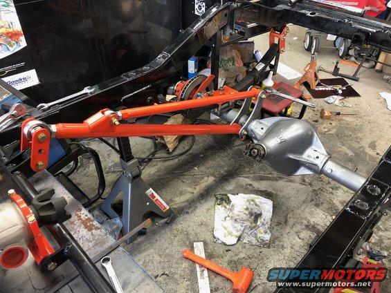
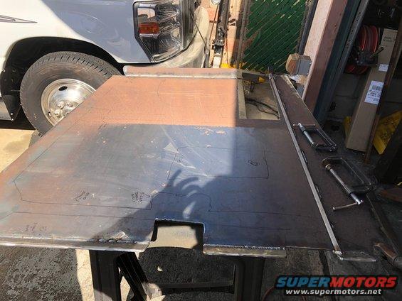
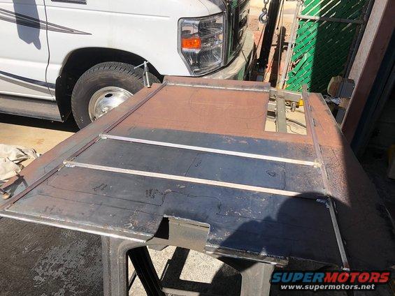
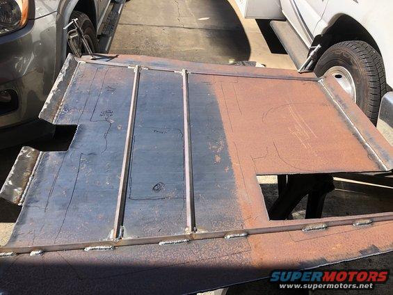
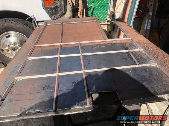
What's new

Build, The General Lee, Tons, 40s, stretch, leaves

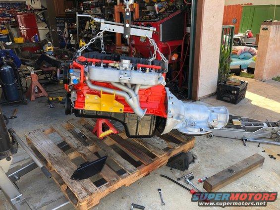
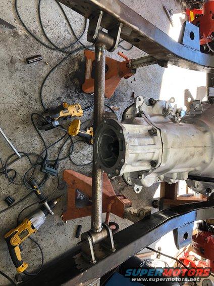
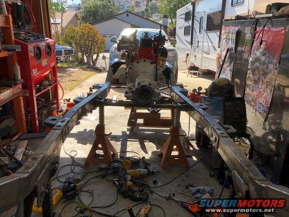
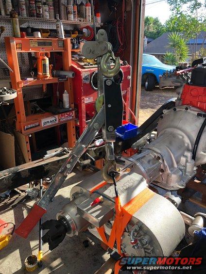
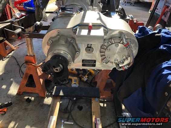
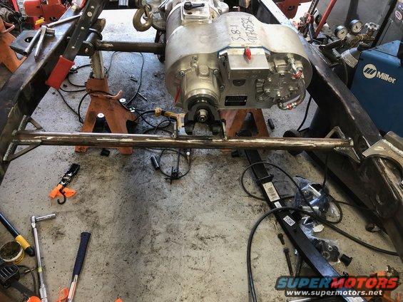
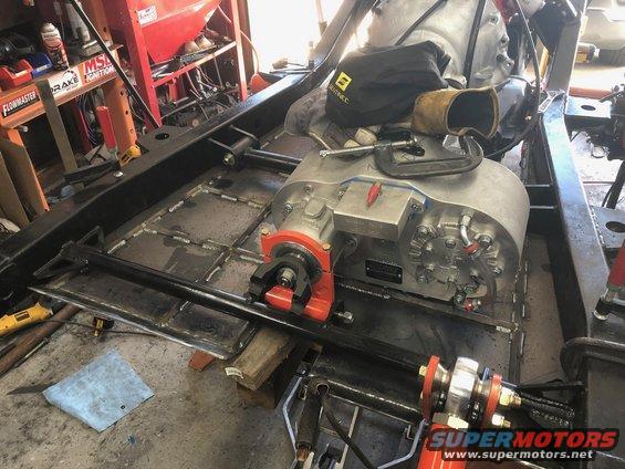
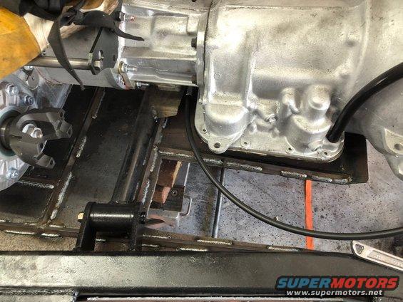
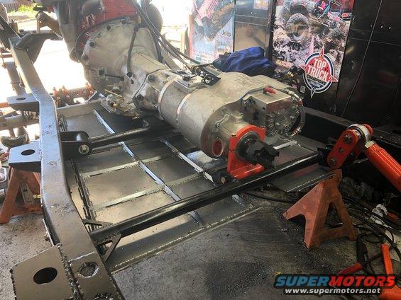
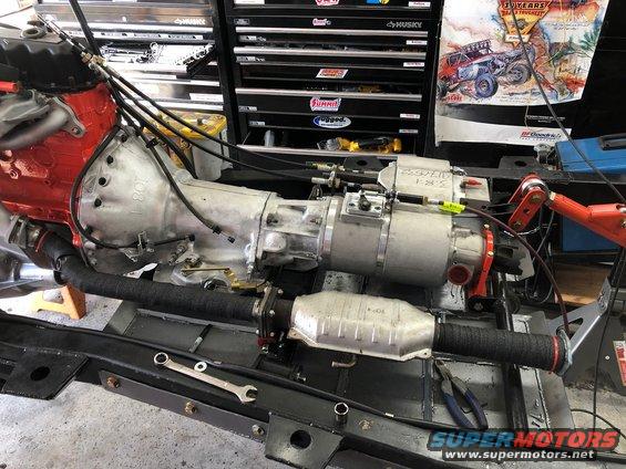
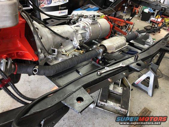
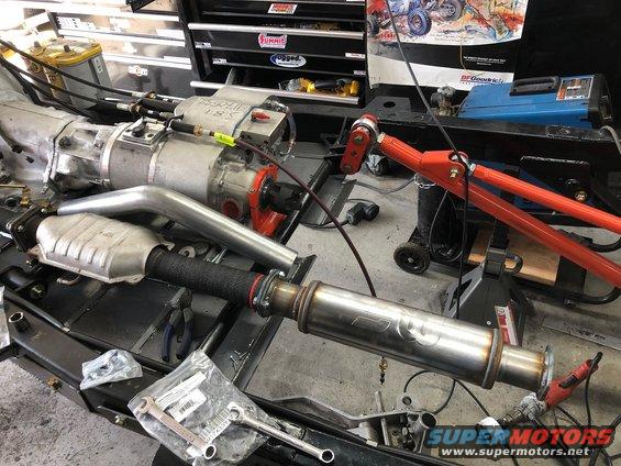
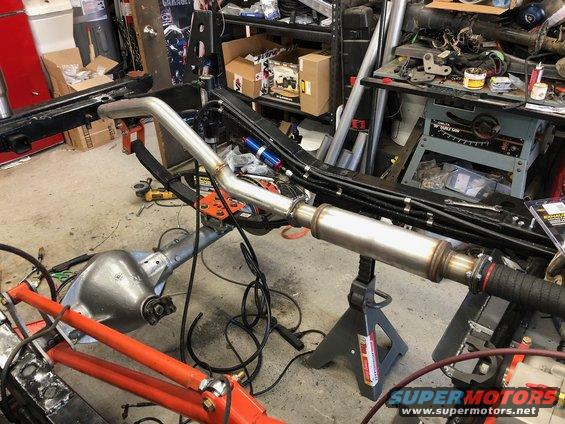
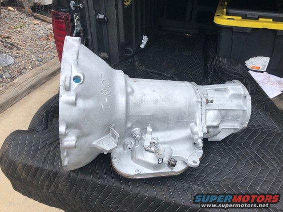
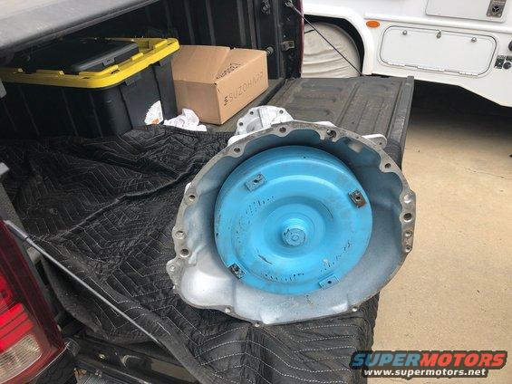
Well I ran down the hill this morning to pick up the transmission. They even painted the thing for me! Amazingly the owner of the shop said it actually wasn’t too bad internally despite me beating on the YJ like it owes me money for years and never really touching it other than the occasional fluid change.

746ac6266ab049e8bcb52c78db529398.jpeg


03ad76636855467c81b70322f059352f.jpeg


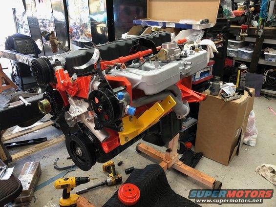
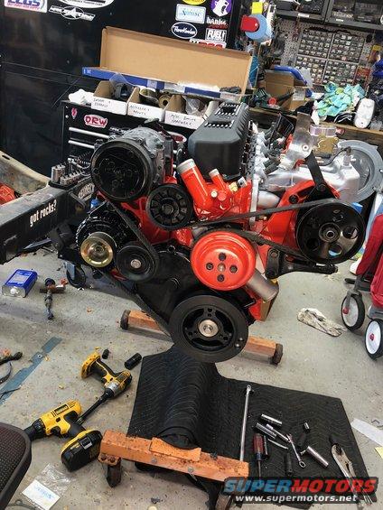
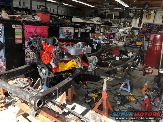
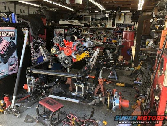
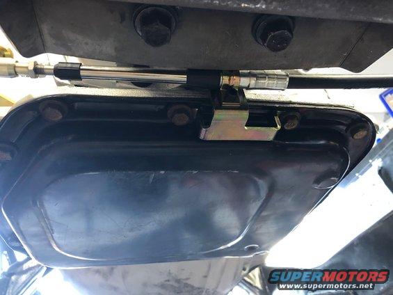
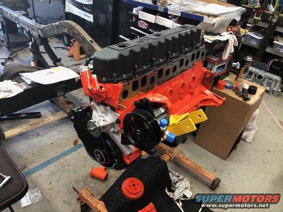
Last night my 5 year old said she wanted to work on the Jeep so we went out to the garage and started putting the engine together. Note for anyone assembling a 4.0 down the road, put your timing cover on FIRST! Then do the oil pan. I spent way too much time fighting to get the timing cover on after the pan. Wound up just dropping the pan again. Luckily I wound up with a second oil pan gasket.the motor came with one as did the new pan I bought.

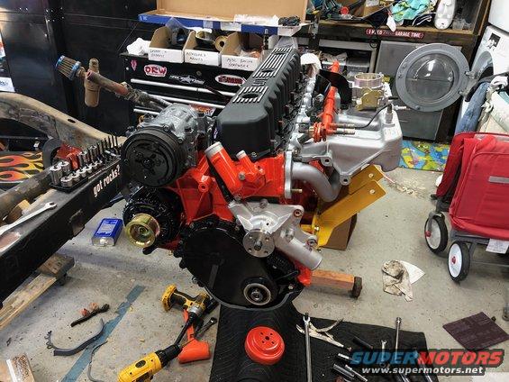
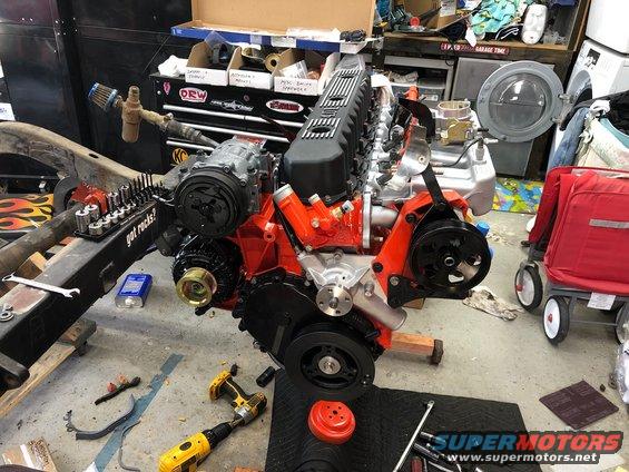
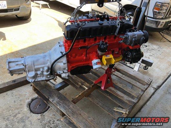
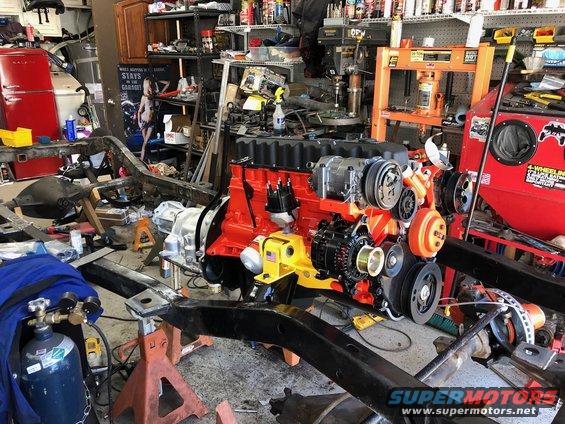
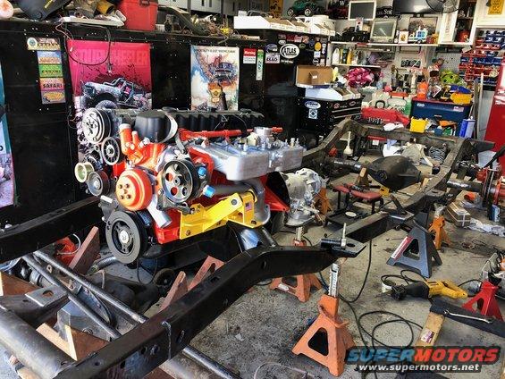
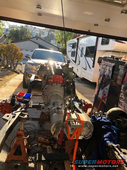
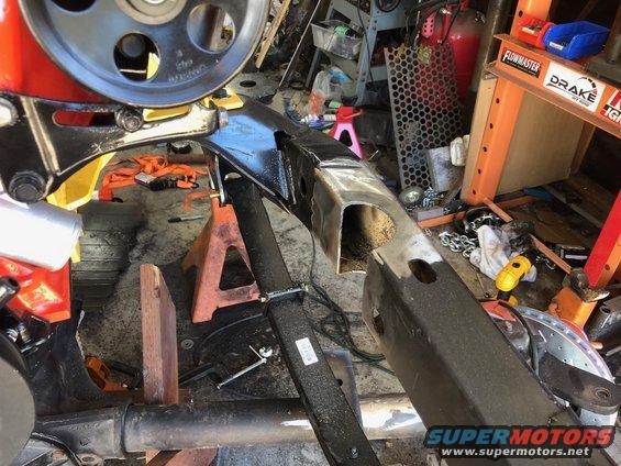
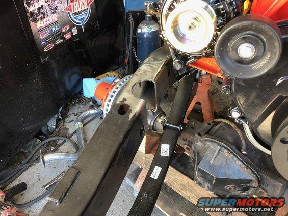
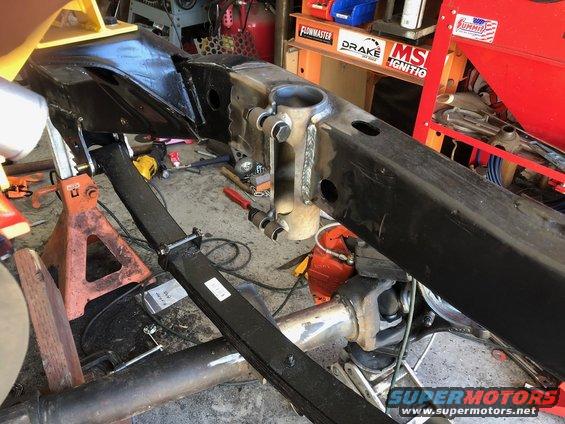
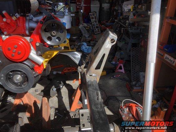
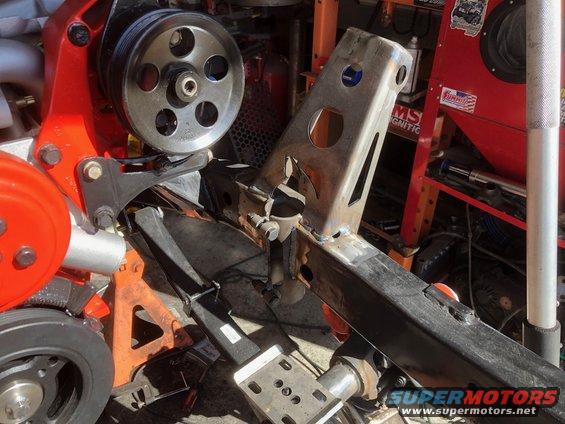
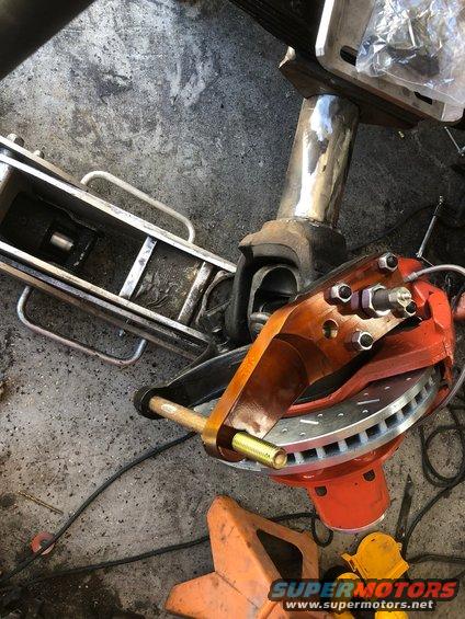
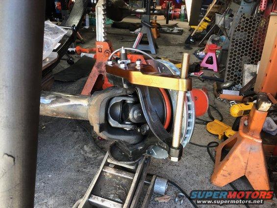
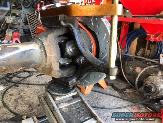
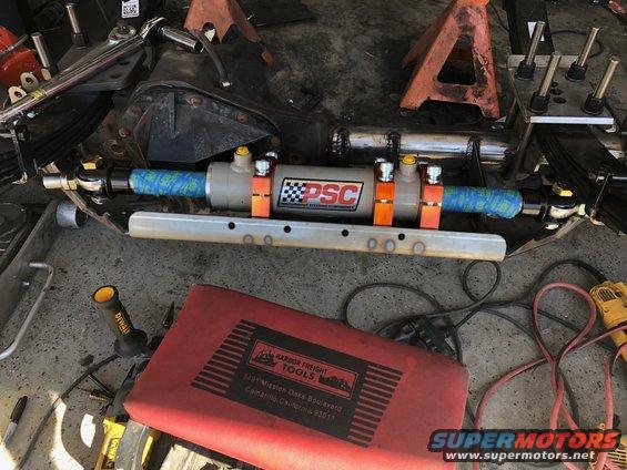
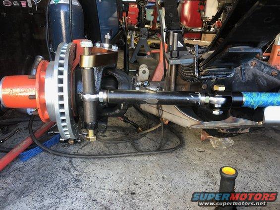
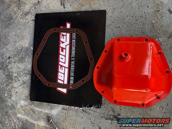
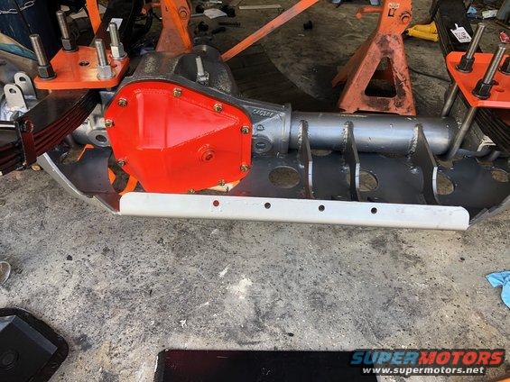
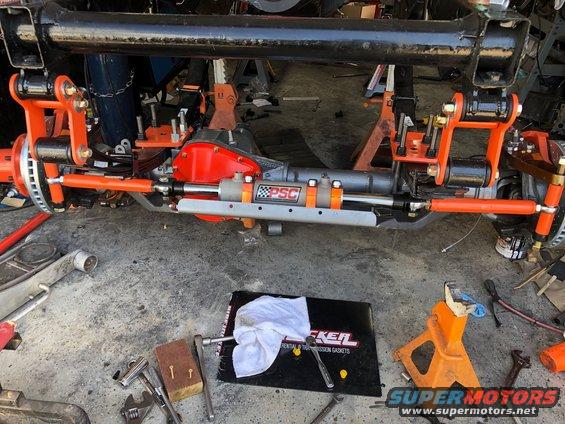
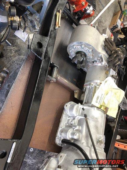
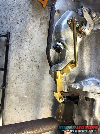
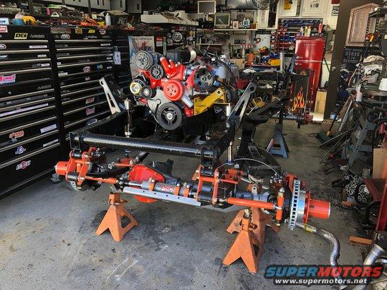
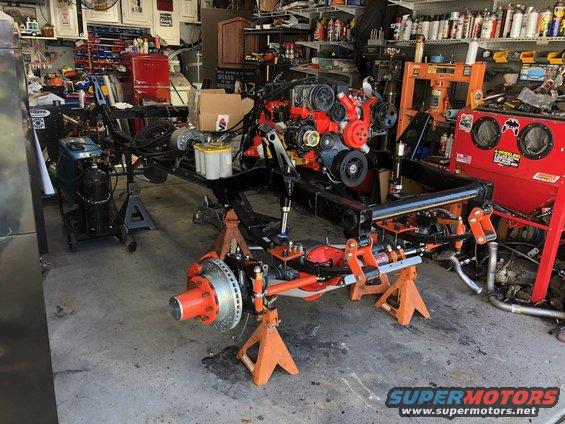
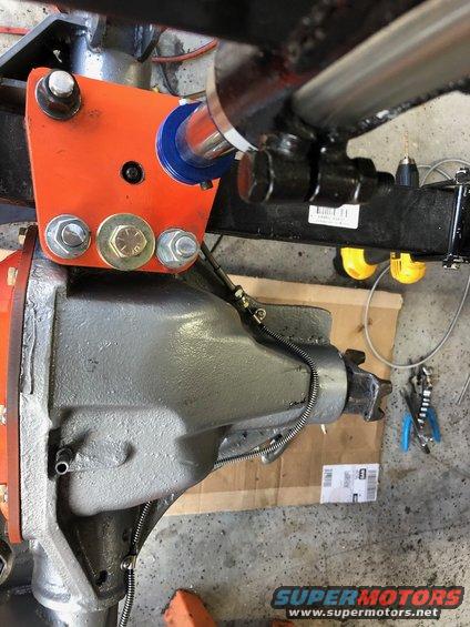
As of right now I have both Brown Dog engine mounts installed on the block, the oil pan, the coil bracket, dipstick tube, valve cover, oil pan, timing cover, Flowkooler Water pump with a new bypass tube, thermostat and Hesco high flow thermostat housing. Oil pump and pick up, power steering bracket and the PSC power steering pump. When we get back from chores later today I am hoping to wrap up most of the component installation.
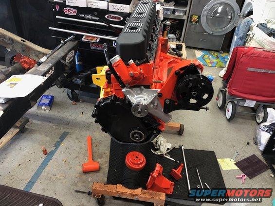
1b6c5b89a8b34aa5882ae15a58323c53.jpeg


7c0ba6cf9351468aaa8f22996f87b57c.jpeg
 
Well as usual I didn’t get quite as far as I wanted to today. However I did get the engine as assembled as it is going to be before dropping it between the frame rails.

First I put the intake manifold back together. New manifold pressure sensor installed, the new 27 lb and hour 4 hole fuel injectors, new fuel pressure regulator, the BBK 62 MM throttle body, etc.

bbf3fb9659124a3381ef052c069bb135.jpeg


Then I started bolting more stuff on to the motor. Got the Banks header, I take manifold, new harmonic balancer, freshly painted AC compressor (for my on board air system) Powermaster 170 amp alternator, idler pulleys, fan belt, new temp sensor, etc all bolted on and locked down.

5fe5c2a691a2479fafcfdcd7b9b53589.jpeg


edb1dee555f44b07a6091a52f3fd7f29.jpeg


133aa91ae65d4ae4abb45ad43298d4ca.jpeg


b2cfbfbc41bb4b6e85aaa2730c19bd95.jpeg


After all that I really did want to bolt the trans back on, but I decided to be on the safe side I’d be better off getting one of my buddies over to help man handle the motor and trans around. So next weekend I have a buddy coming by to help me with all that and getting it between the rails at last.

So in the meantime I went ahead and finished grinding the last rough spots of the frame down smooth and started drilling and installing nutserts in the frame that will be used to secure the fuel and brake lines. I decided it would be easier to do that now before the drivetrain goes in so I got that out of the way real quick.
 
Wasn’t expecting to see these just yet but today I came home to half of my bumpstop order.

98d918c9fb8141cebf8bc243ed38546a.jpeg


2” diameter 4” stroke

And yes, I am going to run air bumps with leaf springs.
 
Ok, super productive day today and a lot to unpack. So bear with me as this is gonna be a couple of posts.

First thing I did was address the rotted out grille mount while I was waiting for my buddy to come over and help me with the engine install. Piece of 1/8” plate with a fresh body mount hole cut in it burned in over the rotted steel.

58cced96f48a4aa5878962610ceee84d.jpeg


b81febc26fe149d48063a45bd7cd4359.jpeg


Then my buddy showed up and we got to work installing the flexplate and the transmission to the engine.

714b73442ed04598abf0d59b5ce0ee1b.jpeg


5b9e12108fe943cba7c56fb9c0bcce36.jpeg


Then we went ahead and maneuvered it in between the frame rails and got it locked down on the new Brown Dog motor mounts.

ada685ed6efa4f79a36f27759e11f829.jpeg


91d2508f5a474a5aaa9be40a55caf73b.jpeg


232efd8db6b642f680a182238f43d1de.jpeg
 
Once the engine and trans were between the rails I went ahead and supported the tail housing of the transmission with a ratchet strap to the rafter in the garage to give me room to work underneath it to fab up the crossmember.

For the crossmember I used the Ruffstuff universal crossmember mount kit, their giant trick tab, and some 1.5” DOM tube.

The Ultra beefy 1/2” tabs burned into the frame

f1713d26c7d34106ba8439f051e5c756.jpeg


83f9ec26cdd44fe3ada927953b7975c3.jpeg


The crossmember I knocked together. Not painting it yet as I may build off of this a bit to support the Atlas.

9f22feeb9d234ab8950c201611b6d669.jpeg


Installed. Flat belly shouldn’t be a problem.

b0c6961f79c1445babaec9b46835c623.jpeg


90fe2ce2621c499c885031edf91285cc.jpeg


2484d12059bd4df4b225ae5baef59aff.jpeg


1697077b8b2945329f729fb5658bbb17.jpeg
 
Running out of energy I made a final push. I raised the frame up to roughly ride height though I think it will be a bit higher. At least gave me enough clearance to slap the axles under the frame and finish burning in the spring and shackle hangers.

I got some measurements from a couple other YJ owners and set the Motobilt spring hangers up so the center hole of the hangers is at the factory distance from the shackle hanger. This way I can move the spring eye to the outer most hole if I need to to adjust my shackle angles later when it’s under its own weight. Then I went ahead and burned them all in.

37745c44d24542259718b81bd8b8c242.jpeg


904a15e5d5e84354824ec6c7e07f4cde.jpeg


1e09b348ab11465aa28f5db7642d21c1.jpeg


And that’s about where I ran out of steam for the day. I think my next goal is going to be to hang the Atlas off the transmission. Kind of need that in for figuring my pinion angles and such.
 
Well not a very productive weekend this week. I only managed to get 2 hours in the garage. So I went ahead and filled the Atlas, installed the site tube and the studs and went ahead and got it installed.

As usual, working by myself so I had to get a little creative. To get my stud pattern I made a cardboard template of the tailhousing to use to set the bolt pattern for the studs. Got them I stalled in the case and used a dolly to roll it in place under the frame. To lift it into place I decided to wrap a ratchet strap securely around the case. This was my best option as I couldn’t use the studs for the lift or I wouldn’t be able to seat the case. Then I used my now trusty harbor freight come along to the rafters and hoisted it up and swung it into place. Sealed the joint with some red RTV and locked down the studs.

47e57ee4b1ae400dac6681bd7d7d6e3a.jpeg


1b2f731f4e58402cb5221ab5a217ca5a.jpeg


7d88e54525d34a1999bfd518bcfc32b5.jpeg


And yes, it’s flat clocked. Kind of thinking I maybe cutting the floor of the tub a bit under the front passenger seat to clear this sucker.

I am still up in the air on whether or not to add another support for it. It feels pretty solid the way it is, but I dunno, that’s still a lot of weight hanging off the *** of the tranny.
 
Despite the blistering heat today I sucked it up and spent a very productive 4 hours in the garage today. Lots of pics from today so this is going to be another multi post so bear with me.

First order of business and goal today was to get the Atlas support crossmember figured out. After looking at it for a bit I reworked my overly complicated plan. Crossmember is 1.75” 250 wall DOM.
I found out real quick that the TMR support ring is sold long so it can be cut to size. To keep the space for my flat belly I had to seriously cut it down to size.

dbfc1f7052d84dffbb7aa8b04a43dd66.jpeg


6d8899a2fd2047f0be74e9ac37cc5abe.jpeg


With that done I used a pair of Ruffstuff mock up bushings to get it mocked in with the crossmember. Once I was happy with where everything sat I burned it all in. I also added some Ruffstuff gussets to the crossmember where it is welded to the frame. Since my antiwrap shackle Mount is also going on this I wanted to be damn sure it was solid. Overkill? Yeah probably.
1c714e6263594eaf9c9fed1b2bbc401f.jpeg


7f17d3f82f474ec59afadfead59b2eaa.jpeg


7feb0e18801c499f96e0f2b60b3a192e.jpeg


I should have plenty of clearance for the driveshaft CV

5608fe7625af47988e834738cf71a0a2.jpeg


45f681dfd93f4818b3ab15d800d4361c.jpeg


7cf93cc81ebd45fb8d83ce60a5d33621.jpeg
 
Once I had the crossmember finished I decided to turn my attention to getting the rear axle set up.

I quickly discovered the Ruffstuff +2 perches I ordered were NOT designed for the monster 4” axle tubes on the Dana 70.

787be3e2969b40f1bf2152d8aa082ee4.jpeg


As you can see, not even close to sitting flat on the tubes. So clearly modifications had to be made. I cast around the garage for something round that was about 4”s in diameter and found a small spool of welding wire. Traced it out with a sharpie and cut off the excess with the plasma cutter.

7fafd51a56eb43bdac5894271f8f5a5a.jpeg


767799e61f264a438f6cde31f4eb0659.jpeg


Obviously not a prefect fit, but close enough.

c2732578d33840e68855d63e58de30bf.jpeg


Once I had the perches modified I went and centered up the axle as close as I could get it. The 70 has an offset pinion, so bolted the perches to the springs then measured from the brake bracket flange to the perches to center it up. It’s like an 1/8” off but it’s as close as it’s gonna get. So I then went ahead and set my pinion angle by pointing the pinion at the Atlas output and burned the perches in. I figured the pinion will rotate down a bit when the weight is on it, so I tipped it up just a hair to account for that.

351b5fc0401343c58943a3e0fdacbc7e.jpeg


76c7cf7a2d3d438cb999cd160328d19f.jpeg


1673ffbe0e254f119c4980cdebbfcf90.jpeg
 
Last thing I did for the day was start looking at the Antiwrap bar stuff.

Once again I found it necessary to open up the Ruffstuff axle brackets to fit the monster 4” tubes on the 70.

7e8dc483a4c1496e92bc6f57c10ff801.jpeg


Then I started looking at placement. Looking like my options are pretty limited because of the monster pumpkin. This is the closest I can get to the center.

e3fec9be9dff4124ada92013c561377b.jpeg


76bf3c3d034642dbb6390a5a4973ec4c.jpeg


It’s going to have to do. I don’t want to try to weld the bracket to the diff so this is pretty much where it will end up. I also went ahead and used a piece of angle iron to see where the shackle end needed to go and burned that on to the cross member as well.

Then for ****s and giggles I tossed a tape between the Atlas yoke and the 70. That’s a long *** driveshaft for a YJ!

6a370c51b6eb41a396add45fadb71bc8.jpeg
 
Monday means back to work on the YJ today. I kind of jumped around a little bit today but mostly focused on continuing the rear suspension work.

My first goal for today was the anti wrap bar. I started with some mock up bushing sleeves and a washer between them to space the axle brackets apart. I unfortunately only recently realized that Ruffstuff only sent me 1 pair of their aluminum mock up bushings when I had ordered two pairs. I’ll have to get In touch with Dan about that. At any rate. Axle bracket mocked up and burned on to the axle tube.

0d2d683d395146b2a9a8759b7d877918.jpeg


The lower tube Ruffstuff sent in their Hd anti wrap bar kit. Don’t think I’m gonna bend this.

2e6e69f10560442fa67e3f38852a9478.jpeg


Im glad I ordered an extra foot of tube. I wound up cutting the lower bar at 43”s in length.

6476dc9486f64def87d088fc93b435be.jpeg


Didn’t take many pictures of the in between on fabricating the upper bar and what not, but here is the finished anti wrap bar.

d2fe8b91102849f9aa26808f139b7cd7.jpeg


ab4730691377482897cf239a90335a1f.jpeg


7ea01b8f6ab94a34a999973d4a8afe23.jpeg


b00e6c3ef7d2469b99e62562a4edac3e.jpeg
 
The sharp eyed among you will notice the cut in the frame on the passenger side. I also went ahead and started flush mounting the rear air bumps today. I used the trick of a hole saw too and bottom and the cut off wheel to connect the lines to make my cuts.

503f340faca0453dae9e165693caf2f4.jpeg


ffd17d39ba9a4b628fecc06cca3210c8.jpeg


2619e86bd076483194fc6160a59a300e.jpeg


3e38571a5ff346868cef7e5b3c804c87.jpeg


This is ideal for the bumps as they are directly over the spring plates. However, they are kind of directly in the way of where I want to also mount the rear shocks. So I was forced to modify the Motobilt shock towers to fit in place around the air bumps.

41330dbfe1c54019bf7ae21f6bcdc034.jpeg


614893980c82409ca788059fda383955.jpeg


604a380643b44a0dbf254bd109ef8e51.jpeg


I only managed to get the drivers side burned in and done. Will finish the passenger side next week.

I am a bit concerned about how much space I am gonna have to fit the shock. I may be forced to run a wheel spacer in the rear for clearance. I’ll have to wait and see.
 
Back at it today and good progress was made.

First thing I did was finish up the rear passenger side air bump mount and shock mount.

3b10d081dfa545df94f112cc6f5231b3.jpeg


While that was cooling I decided to turn my attention to the front 60. First I went ahead and hacked off the spring perch and old shock mounts.

40c43e82c0fe42728007285d83df3ed6.jpeg


Once again I am using perches from Ruffstuff. I got their Chevy 60 swap kit and it came with a mini lift block of sorts that is desgined to go on top of the drivers side perch to bring it up level with the cast perch on the passenger side. I decided I didn’t want it just rattling around loose so I decided to just weld it straight to the top of the perch. So I ground a nice bevel in it all the way around and made the two pieces one.

f2f32c8d76d34d939b52fe8ac713e3fc.jpeg


aca72e2bf68f451092a78d19071e1e2b.jpeg


Then I broke out the high lift to help me actually get the 60 slid in place under the springs to start mocking it up.

48ee893af4bc4c1fabf4d156ff6e48ad.jpeg


Once I got it under the springs I discovered a problem. The axle looked noticeably crooked viewed from above. Im not entirely sure how, but somehow I had managed to weld in the drivers side spring mount a full inch further back than the passenger side mount! :rolleyes: so there was nothing for it but for me to chop the mount off the frame and move it forward 1” to correct it. Oops.

Once I had that fixed and properly aligned I also noticed the driveshaft angle is gonna be pretty gnarly right now. With the cast in perch all I can really do is shim the thing. So I ordered a set of steel 8* shims to tip the pinion of the front axle up a bit to make it a bit better.
 
With the front axle now mocked in place and me now having to wait for the shims to come in before I can really weld in the perches or shock mounts I turned my attention to the front bump and shock mounts.

Just like the rear, I frenched the cans into the frame over the spring plates. I once again used the hole saw frame chop method.

5e0a829d02be41d9853db8859c902de9.jpeg


2039b4a7117548cdb93ad46aff6f6dce.jpeg


e17de069ba5e4db3bf95a0ac52048851.jpeg


Once again, because I elected to French my cans into the frame, I was forced to modify the Motobilt shock towers to work with them as they also need to occupy the same general space. This was easier for the front as I was not also tipping the towers up but using them at the same angle as they are designed to go. So this time I used the same hole saw I used to make my frame holes for the cans and took a half circle or so out of the bottom to clear the cans.

60e7cd627eae45998fa2bfbe53c7ef92.jpeg


64ab23755a8c49fcb0a274f553495676.jpeg


The last thing I did for the day was to go ahead and install the drivers side Sky manufacturing high steer arm. I used a harbor freight step bit that goes up to 3/4” to ream out the lower knuckle hole. Worked beautifully and went thru it in no time. Then I slapped a new plastic kingpin bushing in and bolted on the high steer arm and set the preload (roughly)

a3c6b4c375984d05b745c357216000d3.jpeg


c058c41ca1684eb7bcac3f344cc9cdba.jpeg


b590ff0fc71b462c96bfaf5795d54a1c.jpeg


I am on vacation this week. So I am hoping to get another full day of work done in the garage tomorrow as well. With any luck I’ll have this as a mostly rolling chassis before my vacation is over.
 
So today most of my time was spent working on the front end. I finished welding in the passenger side upper front shocks tower then turned my attention to the front axle and steering set up.

First I went ahead and burned in the drivers side spring perch. I needed that in place as well as the u-bolts before I could start messing with the Artec ram mount. I knew they designed this for the Chevy 60, but for people running links. So I knew I would have to make some modifications to accommodate installation and removal of the u-bolts. Once I had made the appropriate notches to clear them, I went ahead and mocked in the mount with the ram. With the mount as high as I could get it I was not happy with the clearance between the clevis bolt and the bottom of the spring. I had about a half an inch on each side.

d8a5398c6a444d7c9b6534b8fa39d783.jpeg


ebb40b6479284bd59e4fe4ba74d7cb96.jpeg


As you can see, way too close for comfort. So I stared at it for a little bit and decided to compromise and tip the Artec mount down a bit to give me more room beneath the spring. I also went ahead and clearances the lower area of the mount. I used my plasma to cut the arc out a bit larger and smoothed it out with a flap disc. Much better. I know have an inch of clearance on each side.

ebb3fd7ac8284c0998d2c397397bf24d.jpeg


With that taken care of I went ahead and started burning the mount to the axle. I overheated my welder twice during this process so I still have more welding to do on it. I have to finish the braces and the top side stuff. When I pull the axle out for paint I will flip it over and finish welding the bottom to the tubes.

6fd9e51173704cbc8d375709449aa33b.jpeg


b9678eb368eb4679bfda8e21fc035051.jpeg


c11a249544624491a35c396e6ca97e3e.jpeg


I also realized I need to get some bolts or studs for the cast spring perch holes as I don’t have anything the correct size in house. I think they are a 5/8” coarse thread but I am not positive. And my thread checker only goes up to 1/2”. Hopefully tomorrow I can finish welding the ram mount up and actually mount up the ram and mock up my steering links.
 
Ok so I didn’t get a whole hell of a lot done today. Spent a fair bit of time prepping the house for the weekend as the wife and I are leaving the kids with the grandmas here and heading up to Big Bear to celebrate our ten year wedding anniversary and get a bit of alone time without the kids.

However I did finish welding the braces and such in place on the Artec ram mount. That was where I hit another snag. I went to go lock down the clevises to the ram to start mocking up my steering links and discovered I do not have an Allen wrench anywhere near the correct size to tighten them in with. Anyone know offhand what size these things are? I tried a variety of different bolt heads and nothing really fit right. 3/8” was close but too loose. 7/16” is too big. Guessing it’s metric. So instead I went ahead and installed the passenger side Sky Manufacturing high steer arm and stud. Old vs. new. No idea who made the original arms but I wanted the knuckle tie in style.

a55a9b2206f34614a6d713fb3b6571da.jpeg


3b6a2ff0fbeb4bc58b7d6c90afe6b824.jpeg


For anyone curious I painted these with some orange Duplicolor Metalcast paint. It’s basically a candy clear coat. The more coats you lay the darker the color. They almost have a copper hue to them, couple minor runs but I like how they came out. I painted the Ram mount clamps the same way.

Wife and I will be occupied the next few days so I’ll get back on this sometime next week.
 
Well this was one of those weeks where life got on the way of the build. We wound up getting a new loft bed for my daughter with a desk built in beneath it so that consumed most of my day. About all I had time to do was install the clevises to the ram and mount the ram up on the Artec mount. Was really hoping to get the mini tie rods knocked out and wrap up the steering this week.

4caab1dce7fd4ed09951ffe10e700efa.jpeg
 
Ok so I decided to go ahead and cut the links down a 1/2” each so I have some toe adjustability. So I got the mini tie rods done and welded up.

35eeec6e25ca4939a8a7187c792b6009.jpeg


The. I went ahead and dropped the front axle back out with the help of my cherry picker. I also used it to go ahead and flip the axle upside down so I could finish welding up the Artec hydro mount along the bottom to the tubes.

4d0da7190a1542d7af6e70205658ec0b.jpeg


9031c26ec211494b98d08ac6d36b8685.jpeg


After that I wrapped up from the inner C out with some masking paper and tape in preparation for some paint.

7c763f738f034ea99b3468c81d75ba8d.jpeg


My first coat of choice was Chassis Saver by Magnet Paints, the makers of Monstaliner. It is similar to POR 15 except that this stuff is UV stable and does not need to be topcoated. (I will be topcoating it anyway as I won’t be doing the boring black axle look)

0a81824d153c4c8fa2b37f61c9c04e2e.jpeg
 
For the Chassis Saver I went ahead and put down three thick heavy coats on the bottom of the axle. Tube, diff, and the Artec mount all. I figured this area is going to see the most abuse against the rocks so I went heavy with it. I will also be laying down multiple layers of my topcoat on the bottom when I do that next week.

0d45911c7ae846ebad3bfabe9eacc47d.jpeg


After that cured and dried for a while I rotated the axle back upright and laid down two coats on the top side as well.

15621a77ad9b4a3cb7683f01ba502af1.jpeg


Also did a fair bit of painting of other bits and pieces for the front axle. The Rubicon Express boomerang shackles for the front, the mini tie rods for the Hydro steer, the sleeves for the knuckle bolts, and the front spring plates. Oh and the Ruffstuff diff cover for the front.

f6ba9091ff2748b0bd35c379af2f131f.jpeg


That was about all I managed to get done before I had to go pick up my daughter from school. Next week I plan to drill and tap for the third stud on the spring perch, topcoat the front axle, finish burning in the lower shock mounts on the rear axle and pull it out for the same paint treatment the front got.
 
Well I was hoping to get the front axle wrapped up today and get the rear out and get a couple of coats of Chassis Saver on it, however I only managed to get halfway to my goal. I had a hell of a time manhandling the 60 back up under the Jeep and getting it all lined up by myself. However the 60 is now done and permanently installed under the front of the Jeep!

I started with installing the new Ruffstuff Diff cover and a Lubelocker gasket.

d87346cb30a243c299b599e9a569747c.jpeg


Cover is installed with 1” long 3/8” grade 8 bolts and lock washers. Then I filled it with fresh gear oil as I realized this would be way more a hassle to do once the ram is installed. Also as you can see, for the top coat I went with a grey Hammered finish.

ef08e909476440848a5660419e728320.jpeg


Once the diff was topped up I started getting the Ram in place.

3891633c5f3b44cda1074a4bb14a0ad5.jpeg


Then installed the links, knuckle bolts and sleeves, chopped down the knuckle bolts and u bolts and hit the tops with a flap disc to smooth them out.

81fac5b27245415084aaaef9864d3e30.jpeg


689c07a1eea54ec9b352b1cafccf8dc4.jpeg


b7b1014bd4714dc6b22e30e455ac92f6.jpeg


And lastly I installed the front air bumps and put jack stands under the axle so the front is now sitting on its suspension instead of stands on the frame.

225d99a57c2344ecabd90389f8653fcf.jpeg


I did remove the rear axle and get it in position to start painting it as well but ran out of time for the day.
 
Ok so Supermotors is back up so as promised, here are the pictures from Monday’s work. As I mentioned I went ahead and painted the rear 70 the same way I did the front 60.

c01df467d45d45b38d540b4f0a22b6fd.jpeg


2 coats of Chassis Saver making sure the bottom of the massive diff got some extra coverage.

f4fa0cd6cc8d45d09d0f2b59930885ca.jpeg


Followed up by several top coats of Rustoleum Hammered Grey spray paint with the bottom getting a few extra coats to protect from the rock rash.

7d2f964905e24cad83950f5327a18edb.jpeg


Then I went ahead and got it positioned and bolted back in for good.

8ec6cda093e448f28e3106cc53c931d7.jpeg


9fd65b32bd624c1282c77b1f35ff894e.jpeg


1d475702819748d495afa536370ece14.jpeg


cb3aba6672414ae8ad9c23eb20bb3bf2.jpeg


And reconnected the Anti Wrap Bar

7179d5ea9b0d4f7180bee325fc77f75e.jpeg
 
The other project I got to work on this week while I was waiting for paint to dry was to start work on my flat belly skid plate. I have had this big chunk of 3/16” cold rolled steel sitting in my side alley for about 6 years now. It is leftover from when I built my welding table top. I bought a full sheet at the time with the intention to use the leftover for this exact purpose. Didn’t think it would take me this long to do it, but there you are. Little surface rust on it but I’ll get it cleaned up.

1a500818bdb445ebacb705c6de716c4e.jpeg


First thing was to cut it roughly down to size. I used a scrap piece of angle iron and some C clamps to make a guide rail for the plasma to keep my cuts straight.

490bcd2a265e40c394215b1a1b3a5d67.jpeg


Once I had it roughly the size I needed it I used my aluminum ATV jack and some stacked up scrap 4x4s to raise it up to the bottom of the frame rails so I can sharpie up where I still need to trim along the frame rails. It will basically run from the front of the trans pan to the back of the atlas and the frame bends along this area.

55f28c85228b4548a476ef6ee92b5c85.jpeg


I will cut it close to flush with the outside of the frame rails and then weld maybe a 2” wide strip of 3/16” the length of it on both sides and drill thru and sleeve the frame and secure it with 1/2” grade 8 bolts thru the side of the frame keeping the belly completely flat. Maybe 4 to 6 bolts per side. I am also going to bend the forward and rearward edges up for some rigidity and I have some ribbing to add to stiffen the whole thing up. My goal for next week is to hopefully make a good dent in the fabrication of this skid. I also will cut a large channel for the front driveshaft. In the meantime, here are some more images of the rough in and clearances.

a969dbd3ca0f4dc58d87242c70653852.jpeg


de5e8692c5bc49839f161201d20e4b2d.jpeg
 
Alright well today was fairly productive despite some family stuff chewing up some time today.

First task of the day was to install and set up the cable and linkages on the transmission for the Winters shifter as this won’t be accessible once the skid goes on. What I have read in the past was correct and I did have to slightly modify the bracket for the cable that attaches to the bottom of the transmission pan. There are a couple of reenforcement ridges on the tailhousing of the transmission that the bracket hits on. Wasn’t overly difficult to do. I just cut a little extra material off of the bracket where the cable retainer bolts to and it bolted right in.

59f9a06d21a547e7ad680f239570155d.jpeg


Blue loctite was used on all of the various linkage hardware. I do not want this stuff to vibrate loose on me.

63d09177951a403fa60ecbd0f331df8c.jpeg


After that I went on to working on the belly up skid. First thing I did was take the plasma to it to trim the area that overhung the outside of the frame, make my cut out for the front driveshaft, and clearance areas for the anti wrap bar and rear driveshaft.

7de351449fd64716bf43a78fc9cd2ac3.jpeg


With that all done I took a cut off wheel and scored a deep channel 2”s in from the front and rear edges and bent that 2”s up and then welded it back together to give the skid some rigidity.

a49f010f57fc4af3899d853cab924325.jpeg
 
Then I started working up the support skeleton. I picked up a bunch of cut off pieces in various lengths of 1/2”x1/2” x 1/8” thick angle iron from the drop pile at IMS a few weeks ago for a couple of bucks to use for this purpose.

8d25923a6bc743cd9296cb54243b4cc2.jpeg


7d835c2aeae641f2b5062d8654752740.jpeg


73d3190933a0438f9cc5e0dd3dcf4ab5.jpeg


9a2c3c9e141e420fb0053519fe877f79.jpeg


83f97b46a6e04d09bb02525ce125cbfb.jpeg


deb351a153524093a7219f988f7dda7c.jpeg


c87386dae6d24721bc98ecf146e8511e.jpeg


So I basically framed out the area beneath the atlas to make sure that area of the skid is nice and rigid. I also cut a hole below where the Atlas drain plug is so I can change the fluid in the Atlas without dropping the skid. I still have a fair bit of welding to do on the rib cage of the skid and I still have to do the side panels that will actually attach it to the frame. I think this should make for a nice, rigid, strong skid the way I did it. Hopefully I can get it finished up and painted next week then it will be on to the exhaust, fuel and brake lines and Atlas cable shifters. Then when all that’s done it will be time to start test fitting the tub back onto the frame.
 
Back to work on the skid plate today. Lost a bit of time as I managed to run thru the 40 CF tank of MiG mix I just got 2 months ago (a new record, a tank usually lasts me a couple of years) so I had to make a run to West Air for a refill. While I was there I also grabbed a 20 CF tank of Nitrogen as I will need that to fill my bumps and shocks at some point so I figured I may as well grab one since I was there.

So for the skid the first thing I did was sling it back up under the frame and get it all lined back up.

8300ace424bf45a6aa9b1b95444c43fd.jpeg


6b0a63ec025d456bb70685561ab23377.jpeg


Once I was happy with where it sat and I rechecked all my clearances I ripped some more 3/16” steel to 2.5” wide strips to use for the side mounts. Got them all mocked up, made a few cut outs to go around the Swag body mounts, tack welded them on good and measured up and marked my mounting holes in the side plates and the frame. Gonna be some serious overkill as I will end up with 6 bolts per side holding this thing on. Three 1/2” bolts and three 3/8” bolts per side to be exact.

63c9dfe34f2b4309975fe610de2d208a.jpeg


Then I dropped it back out and manhandled it up onto the sawhorses again to finish welding in the side plates and smooth out all the remaining rough edges from the plasma cutter.

4190bf9ffddf448c8431674c6708da9a.jpeg


ee2c433179934073a65015f0830f7811.jpeg


Had just enough time to get the top side painted before I had to call it a day to go get my daughter from school. I was going to paint it black, but I still have a couple of cans of Hammered Grey leftover from the axles. So I am painting the skid the same way I did the axles. Couple coats of Chassis Saver making it extra thick on the business side of the skid, and a couple of coats of Hammered Grey. I actually think this will be better long term because it will be easier to spot any fluid leaks on the lighter color.

e2d2ab630a784c54bd756cb20993df39.jpeg


Next work day should see me finish painting and installing the skid and finishing up the Atlas cable shifters hopefully. (I started messing with them a bit today while waiting for the welder to cool down when I overheated it and waiting for paint to dry)
 
So the wife gave me some wrenching time today and I was able to get a fair few things accomplished.

First on the agenda was to finish painting and mounting the skid. I ordered some of those weld nuts that Todd mentioned and decided to modify it up a little. I drilled thru the frame and basically combined those with some 1/2” ID DOM that I machined out a bit to fit them.

646c22f15ec24de9b7b14b4c0ba5f911.jpeg


I didn’t take any shots of them welded into the frame, suffice to say the mounts for this are completely overkill and beefy.

Then I went ahead and installed the skid. Still waiting on my bolt depot order to arrive with the correct length 1/2” grade 8 bolts but I used some longer ones for now just to hold it up in place.

59449bd43d194fc898913603b3b812c2.jpeg


a70fe885a7014aaca67a3f0b460072f5.jpeg


00300fc9406441c38e1d4e09a9cc483d.jpeg


15a76f481e774a18b683c80bbe09e727.jpeg


After I had the skid on I turned my attention to starting the fuel lines. First order of business was selecting a spot for and mounting the fuel filter. I drilled the frame and installed a couple of 5/16” nutserts to attach the mounting clamp for the Russell fuel filter

59659703dc7e484bb9bccb3f0056b17c.jpeg


After that I managed to build the hose from the fuel rail to the filter. That was about when I realized I didn’t order nearly enough hose ends. So I was forced to call it a day and hit the web to order some stuff. Placed orders with both Summit Racing and Jegs for everything I need to finish the fuel lines, brake lines, and hopefully the exhaust.

af22f0dcc45041e3969985025d2905ce.jpeg


Speaking of fuel lines I decided to come back and add the adapter part numbers necessary to convert the factory YJ fuel system over to -6AN for anyone looking to do this in the future.

For the fuel rail adapter fittings to -6AN I used:
Russell part numbers
RUS-640853
RUS-640863

For the fuel pump Adapters I used:
Earls part numbers
EAR-AT165006ERL
EAR-AT165056ERL
 
So not really gonna get much accomplished this week. I have a work trip to Orlando for the week for a trade show. I did receive all my orders with the various and sundry parts I need to finish the fuel lines, brake lines, and exhaust from Summit Racing and Jegs.

As I was putting my various new parts on the shelf I decided it was high time I take a bit of a fab and wrenching break to try and clean the damn garage a bit. I’ve been wasting way too much damn time hunting for tools and parts lately and it’s been driving me nuts. So I spent a bit of time cleaning and purging and reorganizing, returning tools to their boxes, etc today. Should make me more productive when I get back to work.

I can see the floor under the Jeep!

326b1c9582444a61b78d3c910fd889ea.jpeg


1c39760820b44cd5a5c1c606a61d3815.jpeg
 
So I managed to squeeze in a couple of hours work today.

I started with installing nutserts for my fuel line clamps to keep it all attached to the frame. Unfortunately I somehow managed to break the 1/4” head of my nutsert tool while installing one. Guess I oversat it. So that ended that for the day until I get a new one. (Already ordered a replacement).

So I decided to turn my attention to trying to start figuring out the exhaust. I decided I should start by mounting the catalytic converter. So I made up a mounting flange to attach to the trans crossmember.

I took a scrap chunk of 3/16” plate (I have a lot of this) then put the converter on it and traced out the flange.

8cf8e09d83364bd492a1e995d62c2cec.jpeg


A few minutes with the plasma cutter and a touch of smoothing with a flap disc and the drill press net me this.

1b9ed10b375c48ac8a519365fde8e9cb.jpeg


Welded the flange to a chunk of DOM that will house some poly bushings.

72ae4fbdb3c44892a400c606493e48b6.jpeg


And all finished up and installed to the crossmember.

1510cb64aba445fda8b62e4a9bcd287c.jpeg


997fd61cd3b144c5a1ebe3e23fe852e1.jpeg


It’s a pretty good start and having the cat in place enabled me to more or less figure out what to do to connect everything up to each other. Had to order a few more pieces to make it all work though so I have to wait for that to arrive before I can go too much further on it.
 
Got back to work on the beast today. Decided to keep going on getting the exhaust worked out. First task was to decide where I wanted it to exit. Before I had it exiting thru the body but I did t want to go that route this time. After looking at it for a bit I decided to cut a 3” hole thru the frame where the factory shackle hanger was. This should keep the tail pipe well out of the way so it doesn’t get destroyed on the rocks.

Used a hole saw to cut the holes in the frame then sleeved the hole with a piece of 3” exhaust tube I had left over from the exhaust on my Charger. Using 2.5” tube for the YJ so this is perfect.

27c91f9503cb499b98c09e03e1899709.jpeg


805ae2047648467fa13f8973a04e42e1.jpeg


Then I went ahead and welded some header flanges to my Magnaflow muffler. I am setting this up so I can easily remove pieces to service or replace as needed.

3d65ad49446644d39a1a57a51ef1fe11.jpeg


Next task was to figure out and fabricate the midpipe from the header to the cat. Obviously the factory pipe won’t work so I took a stock replacement YJ pipe and an XJ pipe I picked up and kind of chopped them up and welded them together to make what I needed.

99f5591730b14fd18a1f6d51fc6bea4e.jpeg


4c72ba3560e4468c8e179bdbc64297c4.jpeg


Then I bolted the muffler up to the cat which I also welded a flange to.

4247084f1af6452db091f4d76c35be16.jpeg


I got most of the tail pipe fabricated by cutting and combining some pre bent tubes I got from Jegs. Unfortunately I discovered I should have ordered another 45* bend as that would be perfect to connect the muffler to the tail section. So I ordered another one from Summit. Once that comes in I will finish the tail pipe and burn in the hangers.

I also took care of running my rollover vent line to the front and started planning out the brake lines before I had to go get my daughter from school.
 
Pretty productive day today. I started by getting the exhaust finished up.

4718a2ccea574396b7550e1ea445ed29.jpeg


761ee830f2a14bd6908ef81125bb3afb.jpeg


6e862016c9734839a54bd39183e65ad5.jpeg


1610370a28514253871765bc4f39f697.jpeg


Nice and high up out of the way. Should be well protected from the rocks. I am just waiting for my Motobilt order to arrive with the tabs in it. I have to weld one to the frame to attach the rear exhaust hanger to. It honestly probably isn’t even necessary but I planned for it and already welded the exhaust side bracket on so I may as well.

After I finished up the exhaust I turned my attention to the brake lines. I started with plumbing the rear axle. I have a 30” braided SS line dropping from the frame to a trick little T block I got for cheap from Jegs. Shot SS line to the calipers, and 3/16” hardline make up the rest of the runs. And yes I still need to secure the lines under the perches. I just haven’t really thought up a good way to do that just yet.

1e067aba894944a1b60c753ae6f7e36e.jpeg


6a1dc2155311401b8127367593548cf4.jpeg


Front axle is set up the same way with the same materials.

c014e76e02264938a6858ff07a9bf816.jpeg


d8477578af07458db2bdb2a94f0ce976.jpeg


I also ran the frame line from the front to the rear axle with a break and some SS flex lines that will go to the ball valve in my center console that will be my parking brake. I did a few other small odds and ends. I have a few more things to wrap up next week and then I think it’s time to test fit the tub back on and see what all I am going to have to hack up for clearance.
 
Top Back Refresh