dugEfresh25
Member
- Joined
- Jan 17, 2023
- Member Number
- 5956
- Messages
- 6
I have seen several posts on this and for what ever reason (I am assuming trim packages/abs/no abs/locker/limited/blah blah I have different wiring than some of these posts have.
I got a 2000 Toyota 4runner 3.4 manual with a FJ80 axle in the rear. The stock ABS sensors were in the hubs of the original axle. FJ80 rear does not have any speed sensor locations. In result, check engine light and no speedometer.
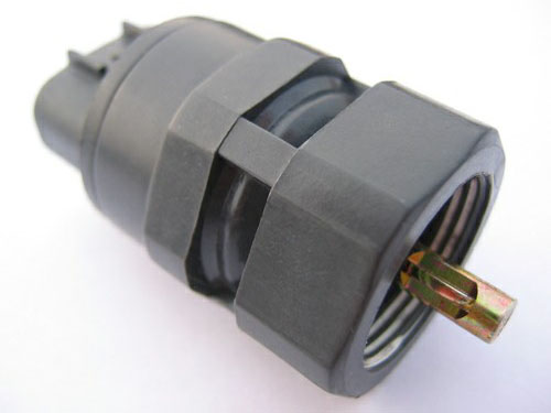
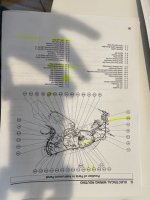
From my understanding, first gen Tacomas have the speed sensor in the rear of the transmission/tcase. Toyota PN# 8318112020. You can then wire this in replacement of the two rear sensors.
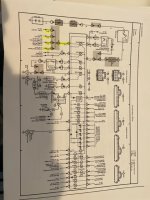
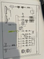
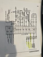
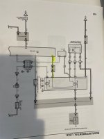
SUPPOSEDLY, the wire you are supposed to TAP into the brown connector at the back of the gauge cluster (Combo meter) specifically C10A pin 1 G-O wire. This wire is labeled to be G-O, but on my 4runner it is actually G-Y. So then I go to where the diff lock ecu is supposed to be where I find the wire harness since I did not have a OEM diff lock. Plug D29 pin 10 G-O. This is actually a G-O wire. At the combo meter, there is a blue connector C11B which does have a G-O wire. These two G-O wires between D29 and C11 have continuity.
I connected 12v +/- to the speed sensor and tested the signal wire. It is pulsing voltage every 4 turns i believe (as specified).
Well this doesn't do anything to my speedometer...
Couple of questions.. There is no reason I should need to actually drive the vehicle for this to work correct? I could simply spin this meter correct? I even turned on the vehicle, put it in gear (with clutch in) and spun the sensor with no luck.
I also question that since my colors are different on my vehicle than these plans AND other write ups on this, whats the issue here?
There was a write up regarding needing to go to put the signal wire to a different pin on C11. I dont want to go throwing voltage somewhere I am not supposed to.
I also read that the ABS ecu accepts the sensor and then converts it to VSS... I am not 100% sure about that either. Can anyone shed light on this please? Thanks!
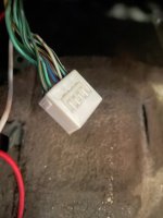
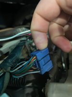
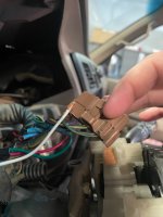
Photos -
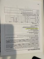
Brown is c10
Blue is c11
white is D29
I got a 2000 Toyota 4runner 3.4 manual with a FJ80 axle in the rear. The stock ABS sensors were in the hubs of the original axle. FJ80 rear does not have any speed sensor locations. In result, check engine light and no speedometer.
From my understanding, first gen Tacomas have the speed sensor in the rear of the transmission/tcase. Toyota PN# 8318112020. You can then wire this in replacement of the two rear sensors.
SUPPOSEDLY, the wire you are supposed to TAP into the brown connector at the back of the gauge cluster (Combo meter) specifically C10A pin 1 G-O wire. This wire is labeled to be G-O, but on my 4runner it is actually G-Y. So then I go to where the diff lock ecu is supposed to be where I find the wire harness since I did not have a OEM diff lock. Plug D29 pin 10 G-O. This is actually a G-O wire. At the combo meter, there is a blue connector C11B which does have a G-O wire. These two G-O wires between D29 and C11 have continuity.
I connected 12v +/- to the speed sensor and tested the signal wire. It is pulsing voltage every 4 turns i believe (as specified).
Well this doesn't do anything to my speedometer...
Couple of questions.. There is no reason I should need to actually drive the vehicle for this to work correct? I could simply spin this meter correct? I even turned on the vehicle, put it in gear (with clutch in) and spun the sensor with no luck.
I also question that since my colors are different on my vehicle than these plans AND other write ups on this, whats the issue here?
There was a write up regarding needing to go to put the signal wire to a different pin on C11. I dont want to go throwing voltage somewhere I am not supposed to.
I also read that the ABS ecu accepts the sensor and then converts it to VSS... I am not 100% sure about that either. Can anyone shed light on this please? Thanks!
Photos -
Brown is c10
Blue is c11
white is D29
Attachments
Last edited: