What's new

Fish Plate Tech

[memphis]

Web wheeler
Joined
Jun 6, 2020
Member Number
1867
Messages
706
My design template and my friends doodle…
I thought I wanted to run the plate along the spring hanger but it’s not adding much of anything except weight

Frame is 1/8”
Fish plates are 3/16” because that’s what I could source

I can add some speed holes with a plasma or hole saw.

What would the hive mind here do differently?

The frame overlap is about 10”
It needs to be finish welded. Do I stitch underneath or run a continuous bead under the plate?
 

Attachments

  • IMG_5414.jpeg
    IMG_5414.jpeg
    1.6 MB · Views: 6
  • 73429975580__4343FA77-E4CC-484F-B21E-B2C4D92C63D5.jpeg
    73429975580__4343FA77-E4CC-484F-B21E-B2C4D92C63D5.jpeg
    220.3 KB · Views: 4
It's not a popular opinion but the two best welders I know, one a bridge welder never fishplated the truck frames they shortened.

After learning more about engineering of beams the top and bottom flanges are allot more important than the webs so if you wanted to you could double those areas and leave the web alone.
Are you saying those two guys would just but weld them together with nothing else, or are you saying they’d plate the overlap top and bottom but not the outside?
 
  • Like
Reactions: DMG
Are you saying those two guys would just but weld them together with nothing else, or are you saying they’d plate the overlap top and bottom but not the outside?
A standard 10" ish formed channel frame would get a backer plate on the inside and fitted up with a appropriate gap and welded.

If the intention was to use the truck in a HD capacity (overload) the bottom flange was "trussed" with another section of flat strap same dimensions as flange spaced with short pieces of the same strap material every 16" or so approximately 2" off the bottom flange from the suspension hanger to as far forward as possible.

I was 18 trying to soak all this info up.
The professional welder of the two (they were brothers) always laughed about fish plates and proclaimed that was to hide lack of talent.

I have used fish plates plenty when I wasn't sure of my material choice or design, just like he said...
 
It's not a popular opinion but the two best welders I know, one a bridge welder never fishplated the truck frames they shortened.

After learning more about engineering of beams the top and bottom flanges are allot more important than the webs so if you wanted to you could double those areas and leave the web alone.
X2 flanges > web
 
And I remember now they cut the beams in a pattern, like a Z pattern but the top and bottom parts are offset, like this

1000012476.jpg
 
Fish plates on the web are useful for doing bolt together stuff and keeping things aligned, useful for sure.

Lots of folks have used them successfully, which is mostly because the whole thing was overbuilt anyway
 
Fish plates on the web are useful for doing bolt together stuff and keeping things aligned, useful for sure.

Lots of folks have used them successfully, which is mostly because the whole thing was overbuilt anyway
I don't think they take away from anything but in practicality maybe not needed.

If the OP is looking to save weight/bulk that area wouldn't hurt my feelings, especially if this rig ends up with a correctly designed front cage.
 
RICHARD TONER has spent entire days giving a truck-frame seminar for the National Truck Equipment Association. He knows that much about truck frames.

Toner, president of Toner & Associates (Pentwater, Michigan) and the NTEA's first staff engineer, said the frame is “the backbone of the truck” because “it carries the loads we put on trucks.”

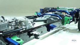
He said most trucks use ladder-type frames with side rails and crossmembers, and the frames are subjected to three types of loads: vertical, torsional, and side.

Side rails support vertical and side loads such as engine, transmission, fuel tanks, battery boxes, suspensions, bodies, work equipment, and cargo. The crossmembers provide torsional rigidity and support components such as the engine, transmission, and radiator. In addition, he said the crossmembers prevent the side rails from twisting with side loads such as the fuel tank and battery box.

“A frame section supported at each end loaded in the middle is in compression at the top and in tension at the bottom,” he said. “There is a neutral axis where there is no stress in the frame. Holes and welding at the neutral axis will not significantly affect frame strength. Holes and welding near the flanges can cause frame failure. Chassis manufacturers restrict the size and location of holes, and most also restrict welding on the frames.”

He said moments are force, or weight, multiplied by distance. One pound times one foot is 1 ft-lb. One pound times 12" is 12 in-lb. They are both the same moment. He said moments on a truck frame can be measured from the front axle, the front end of the frame, or any other point as long as all forces are included. Up forces are positive and down forces are negative.

“The high-moment area is right behind the cab,” he said. “And where do we like to put mounts? Right behind the cab. They're OK if you stay away from the flanges.

“Now you see tractors converted into dump trucks. A tractor frame is not a straight frame. They don't have the right crossmembers to be dump trucks. We seem to pay attention to side rails. We don't pay enough attention to crossmembers. With the same load, the maximum tractor moment is more than twice the straight truck.”

He elaborated on some truck frame nomenclature, saying: a web is the vertical section of a frame rail; a flange is the horizontal section of a frame rail, located at the top and/or bottom of the rail; a centroid is the center of the material in a cross-section of the frame rail; and shear center is the point that takes a vertical load without collapsing the frame rail.

He said yield strength defines the material and is the maximum stress that the material will sustain without permanent distortion. It is related to ultimate strength.

“If it changes shape, you've exceeded the yield strength,” he said.

He said typical values are: 35,000 psi for mild steel, 110,000 psi for alloy steel, and over 110,000 psi for heat-treated steel. When mixing materials of different yield strengths, the lowest value must be used for calculations.

“If I have a frame that is 50,000 psi and reinforcement that is 50,000 psi, use 50,000 yield strength,” he said.

He said the section modulus defines the shape of the frame material in inches to the third power. It is related to the moment of inertia and stiffness. He said published literature can be as much as 30% too high.

“Information is getting better — I will say that,” he said. “But don't trust them. It's not the engineers who are providing the bad information — it's the marketing guys. They can't sell a frame that is 30% less strong than it was last year.”

Toner said ultimate/tensile strength is the maximum stress before failure by separating; dynamic loading is loads put into a frame from acceleration, braking, road irregularities, etc; and fatigue is the behavior of a material when subjected to cyclically applied stress, which can result in a crack and failure.

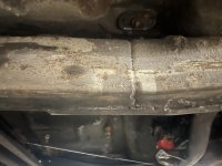
“Fatigue is what kills truck frames — not tensile strength or yield strength,” he said. “Fatigue is when you bend something until it breaks. Every material has an elastic zone. If I bend the material and don't exceed the yield strength, it will come back. If I get past the yield strength, I've strained it. It doesn't go back to the original shape.”

Toner said resisting bending moment (RBM) describes the ability of the frame to resist the moments from the load and truck components; section modulus describes the shape of the material; and yield strength describes the material strength.
Toner said the RBM is the product of the section modulus (SM) and the yield strength (YS) in inch-pounds and is a measure of the capability of the frame rail. He said some manufacturers of equipment such as cranes specify either a section modulus or RBM for the chassis frame. Chassis manufacturers supply frame information with RBM, section modulus, and yield strength in truck data books and body builders books.

So, RBM = SM × YS.

“Why is that important?” he asked. “It describes the maximum load the manufacturer says we can put on the frame in moments.”
 
Reinforcements popular

He said reinforcements are popular because they're easy to put on. But “I'm not big on bolted reinforcements. If you weld it in, it'll be strong.”


Moment of inertia is a mathematical representation of the shape of a frame rail, and is represented by “I.” SM = I/d. And deflection = W × l3/k × E × I.


He said as wheelbases get longer, deflection becomes important. The rule of thumb is that with wheelbases under 160", design for strength; and with wheelbases over 160", design for deflection. For the same load, a 10% increase in wheelbase requires a 10% increase in RBM for strength and a 33% increase in moment of inertia for the same deflection.


“If you're going to lengthen the wheelbase on a chassis, never go beyond the wheelbase the chassis manufacturer recommends without taking a look at it and seeing what you're going to do,” he said.


He said endurance limit is the maximum stress that a material can tolerate indefinitely without failure; fatigue strength is the stress level corresponding to a definite life; and stress concentration is a hole, weld, crack, notch, or other discontinuity that concentrates stress. An open hole concentrates stress from 2.5 to 3 times. A Grade 8 bolt reduces the concentration to 1.5 to 1.9.

“If I'm below, say, 45,000 psi in fully reversed bending stress, I can do it forever and it won't fail,” he said. “If I'm above 60,000, then I have a finite life. You want to stay below the endurance limit.”


Stress concentration is a sixth-power effect when the stress level is above the endurance limit. Doubling the stress decreases the life by a factor of 64, so a 300,000-mile truck becomes a 5,000-mile truck. Increasing the stress by 12% decreases the life by one-half. Decreasing the stress by 12% doubles the life.


“Truck frames are usually modified to change the chassis wheelbase for proper weight distribution,” he said. “Frame modifications are more common on medium- and heavy-duty trucks, although some light-duty chassis are extended for applications such as car carriers. When possible, it is better to move the position of the rear axle than to cut and modify a frame.”


He said fish plates are large flat plates bolted to the web of the frame rail, and are usually 3/8" to 1/2" thick and increase the section modulus considerably. The height of the fish plate often exceeds that of the frame rail. Fish plates are often installed between the rear of the cab and the end of the frame to handle the stresses imposed by a crane mounted directly behind the cab. The ends of the fish plates should be tapered to reduce stress concentration in this area. Fish plates should be bolted using the match-drilled technique so the fish plate and frame act as one. Rivets, brackets, and other components in the area where a fish plate is to be installed will have to be removed and reinstalled with the fish plate in place.


Frame splices

On frame splices, he said the general rule is that reinforcements should taper a minimum of two times the frame height. Volvo recommends a taper of 20-30 degrees; 20 degrees is 2.7 times the frame height, and 30 degrees is 1.7 times the frame height.


He said if the increased wheelbase is less than or equal to the maximum wheelbase manufactured by the chassis manufacturer with the frame on the vehicle, then follow these recommendations:


Single-member rail — the minimum reinforcement should equal the RBM of the original frame rail.


Multiple-member rail — the minimum RBM of the reinforcements should be equal to the RBM of the strongest single member. Splices should be staggered at least twice the height of the frame rail.


Toner's Frame-Splicing Commandments:


Don't go from stiff to flexible. Taper and stagger reinforcements.


Stay out of high moment areas or extend reinforcing to a lower moment area.


Match steels for yield strength as closely as possible.


Extend reinforcements a minimum of twice the frame height past the splice before beginning the taper.


The strength of a frame rail is in the flanges.


More steel is stronger than less steel.


Use a straight cut at the splice.


Toner said the purpose of body mounts is to attach the body to the truck frame without doing more harm than good and retain the body in all horizontal directions.


“Harm can be done by concentrating stress and not allowing the frame to flex,” he said. “Rear mounts could be shear plates or some other rigid configuration that prevents movement. Front mounts should be flexible or placed to avoid stress concentrations and high moments.”


He said mounts can be combined to take advantage of the best features of more than one type. Spacer strips used between the body and truck frame perform multiple functions: cushioning member, sacrificial wear member, and stress-spreading member. Rigid mounts should be used at the rear and flexible mounts at the front. The front mount should not be at the front of the body.


Toner said there are three basic types of body mounts: flexible, rigid, and combination. Rigid mounts should be used at the rear, and flexible mounts at the front.


He said that even though U-bolt body mountings are popular, they are among the least effective mounting systems.


“Are they bad by themselves? No,” he said. “But they don't tend to stay tight.”


He said if they are used, proper frame spacers must be used. Some of the problems are loosening, not preventing forward movement of the body, and frame damage. He said frame flanges should never be notched for a body mount.


“The body should not be rigid at the front,” he said. “It is better to be mounted solidly at the rear and float at the front. Avoid high moment areas for the mounting brackets. Use existing frame holes when possible.
 
IMG_0613.jpeg

When I stretched my samurai I was told by the peanut gallery in my garage I needed to fishplate the frame. The nice thing is the different species of fish really help out for sizing and fitment restrictions, I was lucky and got to use a regular gold fish.
 
Welding frames is basically the opposite of welding roll cages. Execution is everything. Design almost doesn't matter as long as you don't get too stupid. :laughing:

I think it's worth plating because the zig-zag is a big stress riser and it'd be nice to have less flexing going on there and more going on in the straight areas.

3/16 plate on a 1/8 frame is far from ideal but if you give the plate a much longer taper down to the end it'll probably be fine.
My frame isn’t zigzagged it is literally stacked 2x4 on 2x6 and I tapered the ends to a point. The horizontal contact area as I said is about 10” (you can see the seam through the painters tape)

3/16 is far from ideal because it doesn’t match the thickness of the frame? On the sketched up drawing the red is roughly where the ends of the but joint are. I could extend the front further but the other side seems to extend very far
 
I followed this when I cut the front of my Tacoma off and replaced it with 3/16 rectangular tube: "Extend reinforcements a minimum of twice the frame height past the splice before beginning the taper." I used 3/16 plates welded to the side of the frame like your first pic, focusing on getting as much weld area as possible on it. It survived a hard bind where I was winching and actually bent the factory frame and it failed right under/behind the cab. I did the same thing when I cut the rear of the frame off and replaced it with square tube recently, the only difference was I zig zagged it as much as I could.


I'm not an engineer for the record
 
Last edited:
My frame isn’t zigzagged it is literally stacked 2x4 on 2x6 and I tapered the ends to a point. The horizontal contact area as I said is about 10” (you can see the seam through the painters tape)

3/16 is far from ideal because it doesn’t match the thickness of the frame? On the sketched up drawing the red is roughly where the ends of the but joint are. I could extend the front further but the other side seems to extend very far
Regardless, it's a point where shit will be stressed and move differently and likely not respond well to it. You want that point to be solid and you want the flexing to come on slowly along the straight section. You're basically building the steel equivalent of the coil spring or plastic thing that keeps you from kinking a garden hose at the spigot or the rubber strain relief where a power tool cord goes into the tool.
 
I followed this when I cut the front of my Tacoma off and replaced it with 3/16 rectangular tube: "Extend reinforcements a minimum of twice the frame height past the splice before beginning the taper." I used 3/16 plates welded to the side of the frame like your first pic, focusing on getting as much weld area as possible on it. It survived a hard bind where I was winching and actually bent the factory frame and it failed right under/behind the cab. I did the same thing when I cut the rear of the frame off and replaced it with square tube recently, the only difference was I zig zagged it as much as I could.


I'm not an engineer for the record
Can you share a pic? I feel like I’ve seen it before but I can’t remember the thread? Maybe it was in my leaf spring thread
 
And I remember now they cut the beams in a pattern, like a Z pattern but the top and bottom parts are offset, like this

1000012476.jpg
This is how we do big frame splices. Per the Paccar manuals, you should add a channel into the splice as well.

For smaller stuff, I do the frame cuts this way, they do a diamond shape fish plate on the outside of the web, leaving the flanges welded, but alone.
 
The build thread: 2002 TuRD

I also used an Allenfab build thread on the old site as a guide as well. His is a little cleaner and less "cut everything by hand with an angle grinder" and more nicely cut fish plates :laughing:
 
Spoke with Carl Jantz tonight as I couldn’t find his thread on the unnamed site

Saved some pictures of his for reference. He suggested capping the entire top and bottom of the frame/flange as someone posted here in the long text post… the idea makes sense. Carl said his frame still cracks.

It looks like his is capped with 2.25” flat bar, I thought he said 2.5” but it’s some crazy high tensile strength stuff (can’t remember what spec he mentioned but he needed special mig wire to weld it and the steel was stupid expensive a decade ago)
 

Attachments

  • IMG_5423.jpeg
    IMG_5423.jpeg
    502.5 KB · Views: 3
  • IMG_5422.jpeg
    IMG_5422.jpeg
    266.3 KB · Views: 7
Doing a little more research on this since I can’t wrench at the moment. Factory Ram 1500 frame splices on the front and rear… look between the green body mounts. The type of splice is different than what I have done but it looks clean!
 

Attachments

  • IMG_5426.jpeg
    IMG_5426.jpeg
    154.9 KB · Views: 2
  • IMG_5427.jpeg
    IMG_5427.jpeg
    99.5 KB · Views: 6
What engineers who have all day to fuck around with simulation software and FEA software do is not necessarily what you, without that software and all day to fuck around can copy...
 
What engineers who have all day to fuck around with simulation software and FEA software do is not necessarily what you, without that software and all day to fuck around can copy...
I don’t believe I can mimic that whatsoever but looking at S10 splices, what I posted above… I feel like a smaller plate and capping the top and bottom of the frame as suggested here is the best hybrid approach.

The OEMS don’t use plates… they are more or less butt welded
 
I don’t believe I can mimic that whatsoever but looking at S10 splices, what I posted above… I feel like a smaller plate and capping the top and bottom of the frame as suggested here is the best hybrid approach.

The OEMS don’t use plates… they are more or less butt welded

They're not butt welded. Look under any truck or full frame SUV, even JKs, JLs, and JTs. They're all like this. It's two pieces slid into each other and the larger, over lapping piece is "C" shaped and welded to the inner piece.
 
I don’t believe I can mimic that whatsoever but looking at S10 splices, what I posted above… I feel like a smaller plate and capping the top and bottom of the frame as suggested here is the best hybrid approach.

The OEMS don’t use plates… they are more or less butt welded

modularity for OEMs. no need for 5 different frames, just change the middle section for different wheelbases
 
They're not butt welded. Look under any truck or full frame SUV, even JKs, JLs, and JTs. They're all like this. It's two pieces slid into each other and the larger, over lapping piece is "C" shaped and welded to the inner piece.
This is factory S10. This is butt welded together and is boxed on the inside that ends in a < type of pattern
 

Attachments

  • IMG_5429.jpeg
    IMG_5429.jpeg
    2.1 MB · Views: 6
Last edited:
They're not butt welded. Look under any truck or full frame SUV, even JKs, JLs, and JTs. They're all like this. It's two pieces slid into each other and the larger, over lapping piece is "C" shaped and welded to the inner piece.
Agree even the Scout Terras and Travelers in the 70s were done this way, I took a 118" wheelbase one cut the sleeves out shortened them mimicking the stock design, tapped em back on welded back up to make a 100" WB frame.
 
Top Back Refresh